Why. With
the proliferation of embedded systems and the pervasiveness of the
internet, it
is only natural to connect the two. IoT is the combination of embedded
systems,
which have sensors to collect data and actuators to affect the
surrounding, and
the internet, which provides for ubiquitous remote and secure
communication.
Traditional education on wireless communication focuses on the theory
of
communication, which is appropriate for those engineers destined to
develop new
channels and maintain existing ones. However, it is likely for the
embedded
system engineer to be asked to connect devices to the internet. Therefore,
we should add wireless
connectivity to our students’ toolbox so they will be
competitive in the job
market.
Pedagogical
Shift. I am a strong advocate
of
bottom-up education, which means we start
with the basics, teach a topic until the student has full grasp, and
then
encapsulate and use that topic as we move to teach a higher-level
topic. In
order to connect to the internet, our device must implement a plethora
of
details to be fully compatible. The only way to add wireless to an
existing
embedded system lab is to violate the bottom up rule
“students must understand
everything about the devices they use” and provide them a
working “black box”
with which they can experiment. More specifically, we will purchase a
hardware/software solution (called an internet stack) that is internet
ready,
and we will provide a rich set of example solutions to teach how the
internet
works at the component level. Students will modify and combine these
examples
to design systems. This purchase-and-use design process is prevalent in
industry, so it will be beneficial for students to be exposed to both
bottom-up
and component-level design processes.
What. I
added an IEEE802.11 lab where one microcontroller collects data, and a
second
microcontroller displays the data. Data are transmitted across a
wireless
network using UDP packets. I used two EK-TM4C123-GXL LaunchPads ($13
each), two
SimpleLink™ Wi-Fi® CC3100 BoosterPacks ($20 each), one optional Sitronix ST7735 LCD ($20), and a standard wireless access point ($30). This
means the cost of entire lab configuration costs only $30+$86/team.
Video Demonstration of Wireless System
How. The
approach for implementing a smart object over Wi-Fi is to begin with a
hardware/software platform that implements IEEE801.11 Wi-Fi. The
CC3100BOOST is
a BoosterPack that can be used with the MSP430F5529 LaunchPad, the TM4C123
LaunchPad, the TM4C1294 LaunchPad, or a CC31XXEMUBOOST emulation
module. The
CC3100BOOST implements the internet stack with a combination of
hardware and
software components. Software in the LaunchPad preforms system calls to
the CC3100BOOST
to affect wireless communication. I didn’t use the
CC31XXEMUBOOST emulation
module because I didn’t want or need to reprogram the CC3100
BoosterPack. In
this lab students use two EK-TM4C123-GXL LaunchPads and develop a
solution that
transmits UDP packets from one smart object to another. UDP is simpler
than TCP
and appropriate for applications requiring simplicity and speed.
Furthermore,
to use UDP the application must tolerate lost or out of order packets.
UDP
provides a best-effort datagram delivery service.
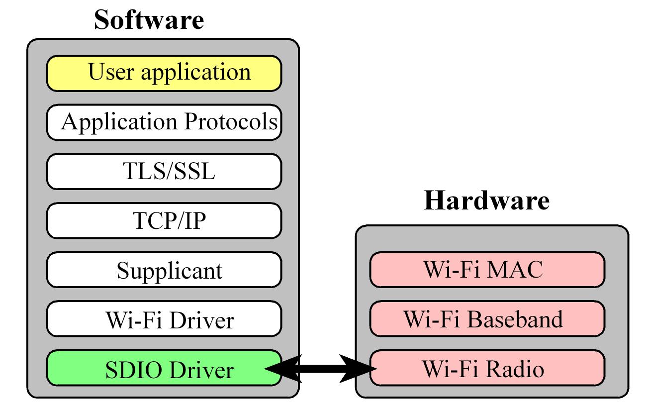
To illustrate how simple it is to implement Wi-Fi, consider the traditional solution running on a typical system. The following figure illustrates the internet stack, which is a sequence of hardware and software layers, allowing the application to communicate over a wireless link. To implement the traditional system requires a high-speed processor with large amounts of memory.

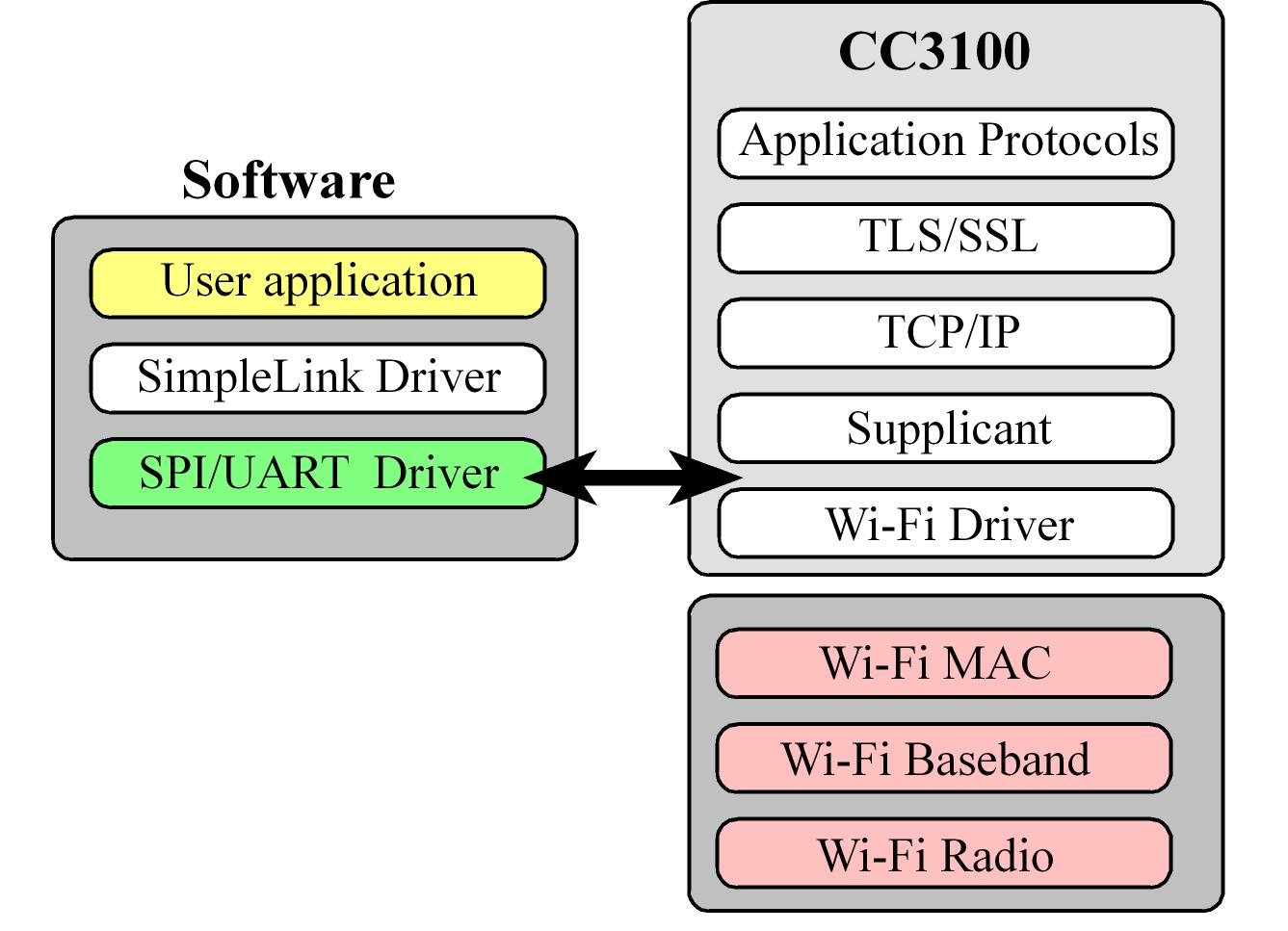
In contrast, consider the stack when using the CC3100. Many of the layers are shifted into the CC3100 firmware, allowing the implementation of a wireless system on a microcontroller with modest speed and little memory (7K flash, 700B RAM). However, the real simplicity comes with the rich set of starter applications, from which you can build your solution. These examples are listed at the end of this blog. The example presented in this blog was derived from the UDP example. With a little help from Austin Blackstone was able to be up and running in a couple of hours. Running the interpreter during initial testing made for smooth sailing.

I gave my students
the ek-tm4c123gxl-boost-cc3100_basic_wifi_UDP
starter project that implemented a simple communication channel and
asked them
to test this project and then to extend it to have more features. You
need to first
download and install Tivaware from http://www.ti.com/tool/sw-tm4c . Find the directory with
the examples\boards. E.g.,
C:\ti\TivaWare_C_Series-2.1.0.12573\examples\boards
Next, you have two choices to download these Wi-Fi starter projects
Unzip these projects and place them into
the Tivaware examples/board
so the
directory tree looks like this:
TivaWare_C_Series-2.1.0.12573
examples
boards
CC31xxxx
ek-tm4c1294xl-enet_uip_temperature
ek-tm4c123gxl-boost-cc3100_basic_wifi_UDP
To get the ek-tm4c123gxl-boost-cc3100_basic_wifi_UDP
project to run, the first set of steps involve hardware devices:
0) First, you will need to configure a wireless access point as
unencrypted.
Give the AP a name. In the starter project you will notice my AP was
called Valvano.
1) You will need to build hardware for the server. The server smart
object includes
a LaunchPad, a CC3100 BoosterPack, and an LCD display. I used the Sitronix ST7735
color LCD
from AdaFruit http://www.adafruit.com/products/358
2) You will need to build hardware for the client. The client smart
object includes
a LaunchPad, a CC3100 BoosterPack, and some sensor interface that creates
an analog
input on PD0. There is an option to stream simulated EKG if you do not
wish to
build external circuits for the client. To send simulated EKG, in lines 69 and 70 of starter.c set the EKG compile flag to 1 and the ADC compile flag to 0.
If you do not wish to buy the LCD graphics you can run the server (display) node with UART output and observe the behavior on PuTTy.
The second set of
steps
involves hardware testing and discovering the IP addresses of the two
smart
objects. Connect a CC3100 BoosterPack to each LaunchPad and plug one
LaunchPad
USB into the PC. Using the device manager discover the COM port
assigned to the
LaunchPad. Then configure PuTTy to run at that COM port, 115200
bits/sec, 1
stop, no parity, and no flow control. The steps are:
1) Change line 59 in starter.c
to
match the name of your AP
#define
SSID_NAME
"Valvano"
//
Open AP name to connect to.
#define
SENSORNODE 0
// true if this node is
sending UDP
packets, using client
#define
DISPLAYNODE 0
// true if
this node is receiving UDP packets, using server
#define
CRTNODE 1
// true if
this node is runs an interpreter on UART0
Video Software steps for setting up Wireless System
The third step is
to edit lines 63-70,
build and download client code to the client smart object. The client is the object with the sensor interface performing ADC input. Set EKG to 1 for
simulated ekg
data, or set ADC to 1 for actual ADC measurements on Ain7 = PD0.
Look
at how simple the client (sensor) code is. In the following excerpt, Lines 15-25
set up
the connection, lines 26-29 construct the payload, and lines 30-31 send
the UDP
segment.
Program 11.2. Client software that measures ADC data and
sends UDP packets (from book).
The fourth step is
to edit
lines 63-68 of start.c,
build and
download server code to the server smart object.
#define
SENSORNODE 0
// true if this node is
sending UDP
packets, using client
#define DISPLAYNODE 1
// true if
this node is receiving UDP packets, using server
#define CRTNODE 0
// true if
this node is runs an interpreter on UART0
The server code is
equally
simple. Power up the AP and two smart objects and data will be
collected on the
client and sent to the server. The UDP payload can be seen in the uBuf[12]
data structure (line 77 in start.c),
which consists of message
type, “=”, and ASCII string data representing the
measured signal. main,
main0,
main1 and main2
are different versions with
varying amounts of UART debugging output and error recovery.
Lab. You can
find the lab assignment I gave to my students at
Lab10B.doc
What’s
Next?
This section lists the sample applications are also provided for
MSP430F5739,
TM4C123GH6PM and SimpleLink Studio. The source code for these examples
can be
found in the examples directory after downloading CC3100SDK, the
SimpleLink
Wi-Fi CC3100 Software Development Kit (SDK) from the TI website. For
more
details on each example, see the docs folder included in the CC3100SDK
download. The CC3100 comes preloaded with CC3100 BoosterPack comes
preloaded
with Out of Box HTML pages. Out of box demo highlights the following
features:
Simple WLAN Connection Using Smart Config, and easy access to CC3100
using mDNS
and HTTP Server.
Antenna
Selection. This is a
reference
implementation for antenna-selection scheme
running on the host MCU, to enable improved radio performance inside
buildings
Connection
Policies. This application
demonstrates the usage of the CC3100 profiles and
connection-policies.
Send
Email.
This application sends an email using SMTP to a user-configurable email
address
at the push of a button.
Enterprise
Network
Connection. This application
demonstrates the procedure for
connecting the CC3100 to an enterprise network.
File
Download.
This application demonstrates file download from a cloud server to the
on board
serial Flash.
File
System.
This application demonstrates the use of the file system API to read
and write
files from the serial Flash.
Get
Time.
This application connects to an SNTP cloud server and receives the
accurate
time.
Get
Weather.
This application connects to ‘Open Weather Map’
cloud service and receives
weather data.
Getting
Started in AP Mode. This
application configures
the CC3100 in AP mode. It
verifies the connection by pinging the connected client.
Getting
Started in Station
Mode. This
application configures the CC3100 in STA mode. It verifies the
connection by
pinging the connected Access Point.
HTTP
Server.
This application demonstrates using the on-chip HTTP Server APIs to
enable
static and dynamic web page content.
IP
Configuration. This
application
demonstrates how to enable static IP configuration
instead of using DHCP.
mDNS. This
application registers the mDNS service for broadcasting and attempts to
get the
service by the name broadcasted by another device.
Mode
Configuration. This
application
demonstrates switching between STA and AP modes.
NWP
Filters.
This application demonstrates the configuration of Rx-filtering to
reduce the
amount of traffic transferred to the host, and to achieve lower power
consumption.
NWP
Power Policy. This
application shows how
to enable different power policies to
reduce power consumption based on use case in the station mode.
P2P
(Wi-Fi Direct). This
application configures
the device in P2P (Wi-Fi Direct) mode and
demonstrates how to communicate with a remote peer device.
Provisioning
AP. This application
demonstrates the use of the on Chip HTTP server for
Wi-Fi provisioning in AP Mode, building upon example application 7.8
above.
Provisioning
with
SmartConfig. This application
demonstrates the usage of TI's
SmartConfig™ Wi-Fi provisioning technology. The Wi-Fi Starter
Application for
iOS and Android is required to use this application. It can be
downloaded from
following link: http://www.ti.com/tool/wifistarter or from the Apple
App store
and Google Play.
Provisioning
with WPS. This application
demonstrates the usage of WPS Wi-Fi
provisioning with CC3100.
Scan
Policy.
The application demonstrates the scan-policy settings in CC3100.
SPI
Diagnostics Tool. This is a
diagnostics
application for troubleshooting
the host SPI configuration.
SSL/TLS. The
application demonstrates the usage of certificates with SSL/TLS for
application
traffic privacy and device or user authentication
TCP
Socket.
The application demonstrates simple connection with TCP traffic.
Transceiver
Mode. The application
demonstrates the CC3100 transceiver mode of operation.
UDP
Socket.
The application demonstrates simple connection with UDP traffic.
XMPP
Client.
The application demonstrates instant messaging using a cloud based XMPP
server.
For
more information see Chapter 11 in Embedded
Systems: Real-Time Interfacing
to ARM Cortex-M Microcontrollers,
2014, ISBN: 978-1463590154, http://users.ece.utexas.edu/~valvano/arm/outline.htm