Chapter 12: Interrupts
Embedded
Systems - Shape The World
Jonathan
Valvano and Ramesh Yerraballi
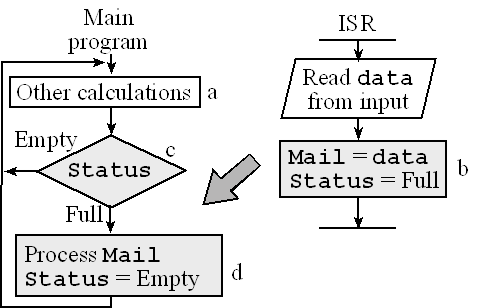
A simple inter-thread synchronization scheme is the mailbox. The mailbox is a binary semaphore with associated data variable. Interactive Tool 12.1 illustrates an input device interfaced using interrupt synchronization and uses a mailbox to send data from ISR to the main program. The mailbox structure is implemented with two shared global variables. Mail contains data, and Status is a semaphore flag specifying whether the mailbox is full or empty.

Figure 12.1. A mailbox can be used to pass data between threads.
Code Blocks, A, B, C and D refer to the blocks labelled (lower-case) in Figure 12.1. The interrupt is requested when its trigger flag is set, signifying new data are ready from the input device. The ISR will read the data from the input device and store it in the shared global variable Mail, then update its Status to full. The main program will perform other calculations, while occasionally checking the status of the mailbox. When the mailbox has data, the main program will process it. This approach is adequate for situations where the input bandwidth is slow compared to the software processing speed. One way to visualize the interrupt synchronization is to draw a state versus time plot of the activities of the hardware, the mailbox, and the two software threads .
Use the following tool to how the foreground and background thread communicate using a "mailbox"
Enter 4-digit hex Data (in the format 0x****):
Using the tool demonstrates that during execution of block A, the mailbox is empty, the input device is idle and the main program is performing other tasks, because mailbox is empty. When new input data are ready, the trigger flag will be set, and an interrupt will be requested. In block B the ISR reads data from input device and saves it in Mail, and then it sets Status to full. The main program recognizes Status is full in Block C. In Block D, the main program processes data from Mail, sets Status to empty. Notice that even though there are two threads, only one is active at a time. The interrupt hardware switches the processor from the main program to the ISR, and the return from interrupt switches the processor back.
Interactive tool 12.2 shows the context switch from executing in the foreground to running a periodic SysTick ISR. Before the interrupt occurs, the I bit in the PRIMASK is 0 signifying interrupts are enabled, and the interrupt number (ISRNUM) in the IPSR register is 0, meaning we are running in Thread mode (i.e., the main program, and not an ISR). Handler mode is signified by a nonzero value in IPSR. When BASEPRI register is zero, all interrupts are allowed and the BASEPRI register is not active.
After pushing the registers, the processor always uses the main stack pointer (MSP) during the execution of the ISR. Events 2, 3, and 4 can occur simultaneously
Use the following tool to see the steps involved in a context switch from the executing the foreground thread to switching to the background thread (ISR) when the Systick interrupt occurs.
Click Start to start the context switch by pushing the current registers into the stack.
Reprinted with approval from Embedded Systems: Introduction to ARM Cortex-M Microcontrollers, 2013, ISBN: 978-1477508992, http://users.ece.utexas.edu/~valvano/arm/outline1.htm
and from Embedded Systems: Real-Time Interfacing to Arm® Cortex™-M Microcontrollers, 2013, ISBN: 978-1463590154, http://users.ece.utexas.edu/~valvano/arm/outline.htm
