Example files associated with the three books
Volume
1 Embedded Systems:
Introduction to ARM Cortex M Microcontrollers Sixth printing
(new 1/2019)
Available
from Amazon
e-book,
Volume 2 Embedded
Systems: Real-Time Interfacing
to ARM Cortex M Microcontrollers
Sixth Printinh (new 12/2017)
Available
from Amazon
e-book
Volume 3 Embedded Systems: Real-Time
Operating Systems for ARM Cortex M Microcontrollers
Fifth Printinh (new 1/2019)
Available
on Amazon
Table of Contents for this
page of example projects
- Introductory Examples (start here)
- Debugging (profiling, execution speed)
- Finite State Machines (Moore and Mealy)
- Human Interface Devices (displays and keyboards)
- Edge-triggered Interrupts (GPIO)
- Serial Interfaces (UART, I2C, SSI, CAN)
- Data Structures (FIFO, heap, linked list, interpolation)
- Timer (Systick, Periodic interrupts, Input Capture, PWM output)
- ADC and DAC Examples
- Advanced Topics (wifi, DMA, FFT, Flash EEPROM, RTOS)
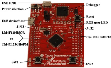
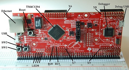
These project files run on the LM4F120, TM4C123, or TM4C1294 microcontrollers and will compile using the
- Keil uVision4 C compiler. The TM4C123 projects in Keil 4/CCS in ValvanoWareTM4C123.zip
- Keil uVision5 version 5.35 and earlier ValvanoWaveTM4C123v5.zip
- Keil uVision5 version 5.38 ValvanoWaveTM4C123v6.zip
Keil
uVision Reference Manual and instructions for download and setup
How to install LaunchPad drivers for
Windows XP,
Windows Vista,
Windows 7,
and Windows 8
To download all
TM4C123 software
Keil 4/CCS ValvanoWareTM4C123.zip or Keil 5/CCS in ValvanoWaveTM4C123v5.zip
(includes all TM4C123 software needed for EE445L, EE445M, book
Volumes 2, and book Volume 3).
To download all
TM4C1294 software
LaunchPadware1294.zip (includes
all TM4C1294 software needed for EE319K, EE445L, EE445M, Volumes 1, 2,
and 3). Click
here to go to EE319K software or Click here
for more information including software for Volume 1. When you
unzip this download, it will create a directory structure
like
the following. Projects with _4C123
in the directory name are written in C99 and will run on the TM4C123 or
the LM4F120. Projects with _4C123asm
in the directory name are written in assembly and will run on the
TM4C123 or the LM4F120. Projects with
_4C1294
in the directory name are written in C99 and will run on the TM4C1294.
Projects with _4C1294asm
in the directory name are written in assembly and will run on the
TM4C1294.
LaunchPadware
driverlib
inc
ADCPrintResults_4C123
Instructions for soldering pins onto the TM4C1294: TM4C1294soldering.pdf
You will need two Samtec 49 by 1, right angle pin headers
TSW-149-09-L-S-RE and TSW-149-08-L-S-RA or
TSW-149-09-F-S-RE and TSW-149-08-F-S-RA
Introductory Examples (start here)
|
Link
to download |
Book |
External
Hardware |
Ports
used |
Description |
| tm4c123gh6pm.h tm4c123gh6pm.s lm4f120.s tm4c1294ncpdt.h |
|
|
All of
TM4C123 or TM4C1294 |
The
header files for TM4C123 and TM4C1294. Defines all the names and
addresses of the
microcontrollers in C99 syntax. These assembly files contain all the
port addresses for the
microcontroller. To use this file, you open this file copy the lines
you need and paste the lines into your program. You cannot include the
.s files, like you can include the header files in C |
| SimpleProject_4C123asm.zip Random_4C1294.zip |
Vol 1, Program 3.2 | none | none | Random number generator using linear congruential generator (LCG) |
|
Example 2.1 |
Solid state
relay |
GPIO |
Provide
functions that initialize a GPIO pin and turn it on and off.
Use
bit-banded I/O. |
|
|
Example 2.2 |
Four LEDs |
GPIO |
Initialize
four GPIO pins as outputs. Continually generate output to drive
simulated stepper motor. |
|
|
Example 2.3 |
One switch |
GPIO |
Provide
functions that initialize a GPIO as input, and allows software to read
the status of a switch. |
|
| InputOutput_4C123asm.zip InputOutput_4C123.zip InputOutput_4C1294asm.zip InputOutput_4C1294.zip |
Section 4.2 | On board switches and LED | GPIO | Functional abstraction of the switches and LED. Switches include internal pull-up resistors. |
| Squarewaves_4C123asm.zip Squarewaves_4C123.zip Squarewaves_4C1294asm.zip Squarewaves_4C1294.zip |
Program 4.4 | GPIO | Continuous output of two pins creating two squarewaves; PG2 version toggles LED every 1 second | |
|
Example 2.4 |
|
PLL |
A software
function to change the bus speed using the PLL. |
|
|
Program 2.11 |
|
SysTick |
Provide
functions that initialize the SysTick
module, wait at least a designated number of clock cycles, and wait
approximately a multiple of 10 milliseconds using busy wait. |
|
|
Example 4.1, Programs 4.4, 4.5 and 4..6 |
Stepper motor |
GPIO, SysTick |
Provide functions that step the motor once clockwise, step once counterclockwise, initialize the stepper motor interface, and turn the motor to the valid desired position. |
Debugging Tools
|
Link
to download |
Book |
External
Hardware |
Ports
used |
Description |
|
Vol 1 Sec 6.9 |
none |
SysTick |
Software dumps port values and time into two arrays |
|
|
Vol 2 Program 3.17 |
none |
SysTick |
Use the SysTick timer to measure approximately how long it takes to calculate a square root. |
|
|
Vol 1 Program 9.13 |
logic analyzer connected to three GPIO pins |
GPIO, SysTick, and Timer 0A |
GPIO outputs used to profile a system with foreground and two interrupts |
Finite State Machines
|
Link
to download |
Book |
External
Hardware |
Ports
used |
Description |
|
PointerTrafficLight_4C123.zip PointerTrafficLight.c PointerTrafficLight_4C1294asm.zip |
Vol 1 Sec 6.5, Vol 2 Sec 3.5 |
Red, Yellow,
Green LEDs, resistors, drivers, switches |
GPIO, SysTick, PLL |
|
| C10_TableTrafficLight.zip TableTrafficLight.c |
Vol 1 Sec 6.5, Vol 2 Sec 3.5 |
Red, Yellow,
Green LEDs, resistors, drivers, switches |
GPIO, SysTick, PLL |
|
| C10_StepperRobot.zip StepperRobot.c |
Vol 1 Sec 6.5, Vol 2 Sec 3.5 |
Stepper motor |
GPIO, SysTick, PLL |
|
|
MealyEngineControl_4C123asm.zip |
Vol 1 Sec 6.5, Vol 2 Sec 3.5 | GPIO, SysTick, PLL | Mealy finite state machine | |
| Vol 1 Sec 6.5, Vol 2 Sec 3.5 | Vending machine with two inputs and two outputs | GPIO, SysTick, PLL | Moore finite state machine. Outputs are produced by function calls rather than simple port writes | |
| Vol 1 Sec 6.5, Vol 2 Sec 3.5 | Robot with two wheels and two sensors | GPIO, SysTick, PLL | Moore finite state machine. |
Human Interfaces (keyboards and displays)
|
Link
to download |
Book |
External
Hardware |
Ports
used |
Description |
|
Vol 1 Sec 4.5 |
UART0 to PC |
UART0 |
Provide functions that initialize the UART, wait for and return a character, and print a character. Uses standard scanf and printf for input/output. | |
|
Section 3.4.5 |
Nokia 5110 |
Uses
SSI0 |
Abstraction
of the LCD as a general purpose output device allowing the use of printf
to stream to the LCD. 48x84 LCD graphics; example can output
characters and draw images on the screen, https://www.sparkfun.com/products/10168 |
|
|
|
Sitronix
ST7735 |
SSI0 |
Start with a
BMP file
convert it to a ROM
buffer in the TM4C, then display it on the LCD |
|
| Kentec_4C123.zip | Kentec EB-LM4F120-L35 | All PortB, PA7-4 | SSD2119 interface on a 320x240 pixels, 16-bit color, 3.5 in, 15 pin | |
|
Section 4.7.1, Program 4.2, Program 4.3 |
HD44780 LCD |
GPIO, SysTick |
LCD interface using 8-bit parallel port mode, blind-cycle synchronization using SysTick timer. Will work with both 3.3V and 5V devices |
|
|
Example 5.4, Figure 5.18, Program 5.13 |
4 by 4 matrix keyboard |
GPIO, SysTick |
Periodic polling synchronization of a keyboard. Row by row scanning of the matrix keyboard occurs during a period SysTick ISR. Data passed via a FIFO. This solution debounces the keyboard. |
|
| AGM1264_4C123.zip | AGM1264 LCD graphics | GPIO, PLL | The LCD-00710 from www.sparkfun is a low-cost graphics LCD. It is 64 by 128 screen interfaced with 12 parallel output pins and is powered by 5V. It interfaces directly to the 3.3V TM4C without level shifters. | |
| GameStarter_4C123.zip | Volume 1 | ST7735 LCD, 4-bit DAC to speaker, 12-bit ADC from joystick, buttons, LEDs | GPIO, PLL, SPI, Timer0, Timer1, ADC | This is a starter project for the EE319K Lab 10 video game. The project has empty files for LCD.s print.s DAC.c and ADC.c. For more information see Lab 10 in the EE319K Lab manual |
Edge Triggered Interrupt Examples
|
Link
to download |
Book |
External
Hardware |
Ports
used |
Description |
|
Program 5.6 |
External switch |
GPIO |
An external switch generates a GPIO interrupt | |
|
Example 5.1, Program 5.7 |
One button and resistor |
GPIO |
Use vectored interrupts to respond to two button presses. Note that button bouncing is not addressed. |
|
|
Example 5.1, Program 5.8 |
Two buttons and resistors |
GPIO |
Use polled interrupts to respond to two button presses. Note that button bouncing is not addressed. |
Serial Interfaces
|
Link
to download |
Book |
External
Hardware |
Ports
used |
Description |
|
Program 4.12 |
Virtual COM port through debugger USB |
UART |
Provide functions that initialize the UART, wait for and return a character, and print a character. |
|
|
Program 5.11 |
|
UART |
Use UART0 to implement bidirectional data transfer to and from a computer running PuTTY. This time, interrupts and FIFOs are used. |
|
|
Programs 7.5, 7.6, 7.7 |
HMC6352 compass or TMP102 thermometer |
I2C |
Provide functions that initialize the I2C0 module to interface with an HMC6352 compass or TMP102 thermometer, send 1, 2, or 3 bytes to a particular slave address, and receive 1 or 2 bytes from a particular slave address. |
|
|
Program 7.3 |
Max549 8-bit DAC |
SSI |
Provide a function that initializes the SSI0 module to interface with a MAX549 8-bit DAC, and use SSI0 . |
|
|
Program 7.2 |
MAX5353 12-bit DAC |
SSI |
Provide a function that initializes the SSI0 module to interface with a MAX5353 12-bit DAC, and use SSI0 to send a 16-bit code to the MAX5353 and return the reply. |
|
| CAN_4C123.zip | Volume 3 | CAN driver | Controller Area Network, CAN | Two TM4C123 boards are interfaced via CAN. The switch position on one board is displayed as LED status on the other. Communication is both directions. |
Data Structures
|
Link
to download |
Book |
External
Hardware |
Ports
used |
Description |
| Float_4FC123asm.zip float.s Math_4C123.zip sqrt.s circle.s |
Vol 1, Sec 7.9 | Floating point examples | ||
| FIFO_4C123asm.zip FIFO.s FIFO_4C123.zip FIFO_4C1294.zip FIFO.c FIFO.h |
Programs 3.7, 3.8, 3.9 and 3.10 | GPIO, Timer0A periodic interrupts | First in first out queue, pointer method and index method Provide functions that initialize a FIFO, put data in, get data out, and return the current size. The file includes an index and a pointer implementation and macros to create more FIFOs. Periodic interrupts are used to verify the FIFO has no critical sections. | |
|
Program 3.11, Volume 3, Program 3.1, Section 3.2.2 |
Fixed size memory manager. Allocate memory block, and deallocated block. |
|||
| Heap_4C123.zip heap.c heap.h |
Volume 3, Section 3.2.3 | Memory manager implementing malloc and free | ||
|
LinearInterpolation_4C123asm.zip |
Volume 1, Program 6.22 | Linear interpolation, sine function | ||
| LLFifo_4C123asm.zip LLFIFO_4C123.zip LLFIFO_4C1294asm.zip LLFIFO_4C1294.zip |
Section 6.6, Program 6.11-6.18 | none | none | Linked list FIFO, dynamic memory manager |
Timer Examples
|
Link
to download |
Book |
External
Hardware |
Ports
used |
Description |
|
Program 5.12 |
|
GPIO, SysTick |
Periodic interrupts using SysTick. Software allows you to select the interrupt period and attach a user program (hook) |
|
|
Example 6.2, Program 6.2 |
|
GPIO, Timer0A |
Use Timer0A in edge time mode to request interrupts on the rising edge of PD4 (CCP0), and measure period between pulses. |
|
|
PeriodicTimer0AInts_4C123asm.zip PeriodicTimer0AInts_4C123.zip |
Program 6.5, Example 6.6 |
|
GPIO, Timer0A, PLL |
Use Timer0A or 3A in periodic mode to request interrupts at a particular period. Uses 32-bit mode. |
|
Program 6.1 |
|
GPIO, Timer0A |
Use Timer0A in edge time mode to request interrupts on the rising edge of PD4 (CCP0), and count the pulses. |
|
|
Program 6.6 |
|
Timer0 |
Use Timer0A in PWM mode to generate a square wave of a given period with 50% duty cycle. |
|
|
|
|
Timer0 |
Use Timer0A in PWM mode to generate a square wave of a given high period and low period. |
|
|
Program 6.7 |
|
PWM0 |
Use PWM0 to generate a 100 Hz square wave with 50% duty cycle. These examples DO NOT run on the LM4F120, because the LM4F120 does not support hardware PWM. |
ADC and DAC Examples
|
Link
to download |
Book |
External
Hardware |
Ports
used |
Description |
|
ADCSWTrigger_4C123.zip |
|
|
ADC |
Provide functions that initialize ADC SS3 to be triggered by software and trigger a conversion, wait for it to finish, and return the result. The TwoChan examples use SS2 sampling two channels with software start and busy-wait synchronization. |
|
|
|
ADC, Timer0A |
Provide a function that initializes Timer0A to trigger ADC SS3 conversions and request an interrupt when the conversion is complete. |
|
|
|
|
ADC, PLL, Timer0A, UART |
Use a setup similar to ADCT0ATrigger.c to gather ADC samples into a buffer. When the buffer is full, print them to the UART separated by TABs. |
|
|
Program 7.2 |
MAX5353 12-bit DAC |
SSI |
Provide a function that initializes the SSI0 module to interface with a MAX5353 12-bit DAC, and use SSI0 to send a 16-bit code to the MAX5353 and return the reply. |
|
|
Program 7.3 |
Max549 8-bit DAC |
SSI |
Provide a function that initializes the SSI0 module to interface with a MAX549 8-bit DAC, and use SSI0 . |
|
|
Vol 2, Program 8.7 |
RC low pass filter |
PWM |
Provide DAC functionality with a PWM output and hardware LPF. The information is encoded as duty cycle and the LPF converts duty cycle to analog output . |
|
Advanced Examples and RTOS code
|
Link
to download |
Book |
External
Hardware |
Ports
used |
Description |
|
CC3100GetWeather_4C123.zip CC3100DataLog_4C123.zip |
Volume 2, Section 11.4 | CC3100 BoosterPack |
UART0, UART1 |
Uses CC3100 to create a smart object, fetches weather data from openweathermap.org. The DataLog version writes data to a server. |
|
ESP8266_4C123.zip ESP8266_SensorBoard.zip esp8266.c |
Volume 2, Section 11.4 | esp8266 |
Port B, E, PLL, SysTick, UART0, UART1/2 |
Uses esp8266 to create a smart object, fetches weather data from openweathermap.org. The SensorBoard version uses UART2 PD7/PD6 as connected in the EE445M Robot Sensor Board. |
|
RTOS_4C123.zip osasm.txt os.c |
Volume 3, Section 4.2 | none |
Port D, PLL, SysTick |
Preemptive Round Robin Real-Time Operating System |
| FixedScheduler_4C123.zip | Volume 3, Section 4.2 | none |
GPIO, PLL, SysTick |
Implement a real-time operating system with multiple periodic tasks |
| ProfileFFT_4C123.zip | Volume 3, Sections 3.7 and 5.6 | none |
GPIO, PLL, SysTick |
Execution of 64-element 256-element and 1024-element FFT, execution profiling of these functions. STMicroelectronics published integer FFT code has part of their STM32F10x_DSP_Lib library. |
| SDC_4C123.zip SDC_4C1294.zip |
Volume 3, Section 6.6, Program 6.4 | Secure digital card | Systick, and SSI | Low-level device driver for secure digital card |
| SDCFile_4C123.zip SDCFile_4C1294.zip |
Volume 3, Section 6.6, Program 6.4 | ST7735R and Secure digital card | Systick, and SSI | Low-level device driver for secure digital card, FAT16 file system, and ST7735R graphics |
| DMASoftware_4C123.zip DMASoftware.c |
Volume 3, Program 6.1 | none | uDMA | Memory to memory transfer using uDMA |
| DMATimerPortRead_4C123.zip DMATimer.c |
Volume 3, Chapter 6 | PORTF input | Timer, uDMA | PORTF to memory transfer using uDMA, triggered by a periodic timer. |
| DMATimerPortWrite | Volume 3, Chapter 6 | PORTE output | Timer, uDMA | Memory to Port E transfer using uDMA, triggered by a periodic timer. |
| DMASPI_4C123.zip | Volume 3, Chapter 6 | MAX5353 12-bit DAC | Timer, SSI, uDMA | Streaming data from memory to DAC/SSI using periodic timer, and ping-pong DMA. |
| Flash_4C1294.zip Flash_4C123.zip FlashProgram.c |
Volume 3, Section 6.5 | none | Internal Flash EEPROM | Erasing the programming the internal EEPROM. |
| SensorTestProject.zip | Volume 3, | All the ports | ADC, CAN, SSI, Timer | EE445M Robot Sensor Board. |
Videos
How
to change the name of an assembly project
How
to build a not gate
Stellaris LaunchPad Tester booster pack and software application designed by Daniel Valvano
Last updated September 1, 2019