Appendix 2. Metrowerks TechArts
9S12C32 Setup
What's in Appendix 2?
What you need to get started
Installing Metrowerks
Instructions for handling the Technological
Arts 9S12C32 board
Development Procedure
Interrupt vectors for the 9S12C32
Web sites for more information.
What you need to get started
Software
You will need to install Metrowerks
CodeWarrior for the 6812.
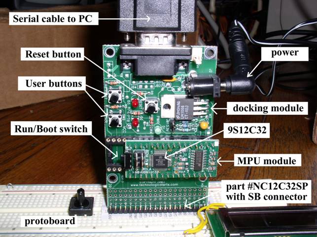
NC12C32SP Development Board Go to the
http://www.technologicalarts.com web site and click the University
of Texas at Austin link (order NC12C32SP). The 2005 cost is $49.95 plus
shipping. This kit includes a 9 VDC
unregulated power source, a 9S12C32 CPU module, a docking module with
0.3in male pins, and a standard
9 pin null modem serial cable (TX RX and GND).
Protoboard
You will need a standard breadboard
into which the 9S12C32 docking module plugs. This breadboard will
contain your external circuits.
Installing
Metrowerks
Installing Metrowerks
1)
http://www.metrowerks.com/MW/download/default.asp
2) select "CodeWarrior Development Studio for HC12 Microcontrollers"
3) fill in name information
email must be correct
decide whether or not you want email from Metrowerks
4) Wait for email, should contain these links
To download your software, please use the following link:
ftp://ftp.metrowerks.com/pub/embedded/HC12/HC(S)12_v3_1.exe
To use your software you must have a license key, please use the
following link to download one:
ftp://ftp.metrowerks.com/pub/embedded/HC12/CW12R31_SElicense.zip
5) Download HC(S)12 v3.1, install
6) Download license, unzip
7) Copy license.bat overwriting existing limited version license
This license is available to all educational users
8) Download starter projects from
http://www.ece.utexas.edu/~valvano/metrowerks/
Interrupt
vectors for the 9S12C32
Some of the interrupt
vectors of the 9S12C32 are
0xFFD6 interrupt 20 SCI
0xFFDE interrupt 16 timer overflow
0xFFE0 interrupt 15 timer channel 7
0xFFE2 interrupt 14 timer channel 6
0xFFE4 interrupt 13 timer channel 5
0xFFE6 interrupt 12 timer channel 4
0xFFE8 interrupt 11 timer channel 3
0xFFEA interrupt 10 timer channel 2
0xFFEC interrupt 9 timer channel 1
0xFFEE interrupt 8 timer channel 0
0xFFF0 interrupt 7 real time interrupt
0xFFF6 interrupt 4 SWI software int
0xFFF8 interrupt 3 trap software int
0xFFFE interrupt 0 reset
Board handling
instructions
1) Do not insert or remove the board while power is
applied.
2) Touch a grounded object before handling CMOS electronics. Try not to
touch any exposed wires.
3) To push the docking
module into the protoboard, push straight down.
4) Never remove the CPU module from the docking module. THE PINS ON THE
CPU MODULE ARE VERY FRAGILE. On the other hand, the male pins on the
docking module have been very robust as long as you limit the twisting
forces. To remove the docking module from the protoboard pull straight
up (or at least pull up a little at a time on each end.)
5) Use and store the system with the docking module plugged into a
protoboard (this will reduce the chances of contacting the metal pins
tied directly to the 6812 with either your fingers or stray electrical
pulses).
6) Do not use the 9S12C32 with any external power sources, other than
the supplied wall-wart. In particular, avoid connecting signals to the
6812 that are not within the 0 to +5V range. In particular, voltages
less than 0V or greater than +5V will damage the ADC.
7) Do not connect any wires to the pins labeled Vin, DTR, TX, or RX.
These pins contain voltages outside the safe 0 to +5V range. Also do not
connect to the Reset pin.
8) Label all your pieces (CPU module, docking module, cable, wall wart,
and protoboard) with your name.
9) Test the CPU/docking module combination by running some of the
example programs found at
http://www.ece.utexas.edu/~valvano/metrowerks/ . Good programs to
test the system are the Moore FSM and the Simple SCI.
Development Procedure
A)
To open an existing Metrowerks project
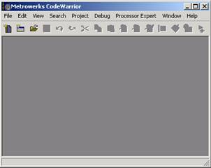
1) Start
Metrowerks CW12 3.1
2) Execute File->Open, navigate to an existing *.mcp file, and click
"OK"
B) How to configure create a new Metrowerks project
1) Start
Metrowerks CW12 3.1
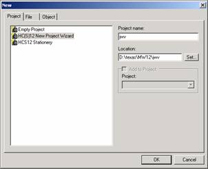
2) Execute File->New, click "Project" Tab
select "HC(S)12 New Project Wizard"
specify the "Project name"
verify its "Location", click "OK"
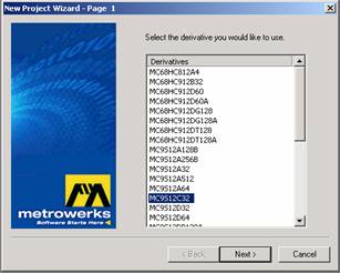
3) Select the derivative you want to use
"MC9S12C32", click "next"
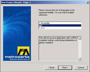
4) Choose the set of languages supported
select "C", click "next"
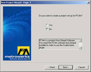
5)
Do you want to create a setup for PC-lint
select "no", click "next"
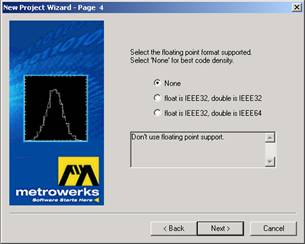
6) Select the floating point format supported
select "None", click "next"
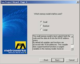
7)
Which memory model should be used?
select "Small"
click "next"
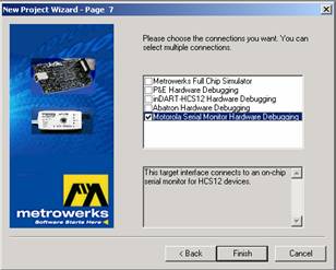
8) Please choose the connections you want
select "Serial Monitor Hardware Debugging"
click "Finish"
9)
Create or copy program files
*.c
and
*.h
place them into the "Sources"
directory of your project
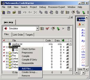
10)
Add the necessary C files to project
click on Sources in the "mcp"
window
right click and execute "Add
Files..."
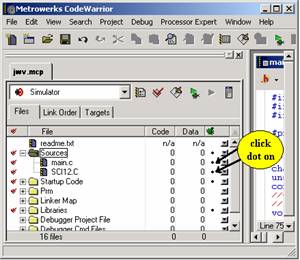
“click dot on” in the field associated all C source files under the
"bug" icon
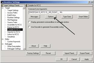
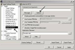
13) Change compiler/linker options
click the right-most toolbar ICON called "Simulator
settings"
click "Compiler for HC12"
choice
click "Options"
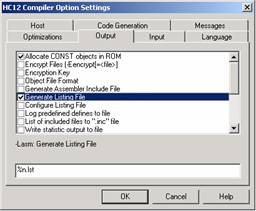
click "Output"
tab
select "Allocate CONST
objects in ROM"
and "Generate Listing File"
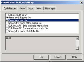
click "Linker for HC12"
choice
click "Options"
click "Output"
tab
select "Generate
S-Record"
and "Generate a map file"
C) How
to run Metrowerks on the Real 9S12C32 board
Do this once
1) Connect
PC-COM1 to the 9S12C32 docking station,
2) Place the Run/Boot switch on the 9S12C32 board in Boot mode
3) Connect power to 9S12C32 docking station.
4) Touch the reset switch on the docking station
For each edit/compile/run cycle for software that does not use SCI
1) In Metrowerks, perform editing to source code
2) In Metrowerks, compile/Link/Load
Execute Project->Debug
3) Click the green arrow in the debugger to start. Runs at 24 MHz.
For each edit/compile/run cycle for software that does use SCI
1) set the Run/Boot switch to Boot mode, push the reset button
on the 9S12C32 docking station
2) execute Project->Debug (compiles and downloads code to 9S12C32)
3) quit MW debugger once programming complete. Quitting the debugger
will release the COM port.
4) start a terminal program (like HyperTerminal)
specify proper COM port, 19200 bits/sec, no flow control
5) set the Run/Boot switch to Run mode and push the reset button on the
9S12C32 docking station. Runs at 4 MHz.
6) when done, quit terminal program. Quitting the terminal program will
release the COM port.
Web sites for more information
Return to Table of Contents