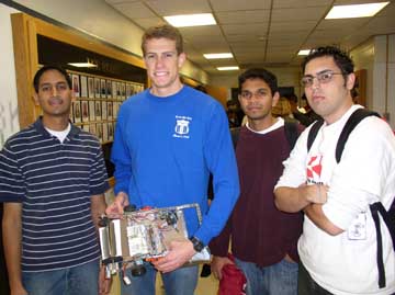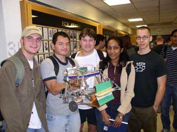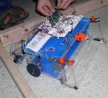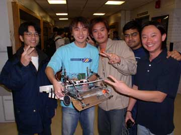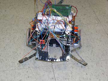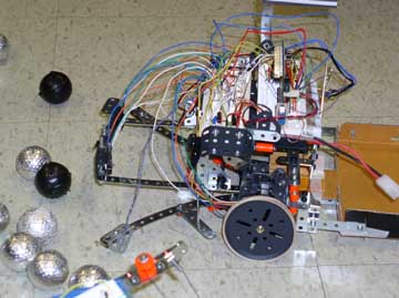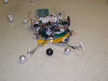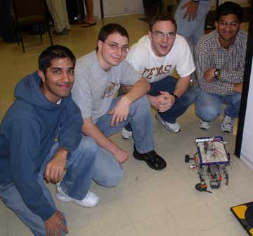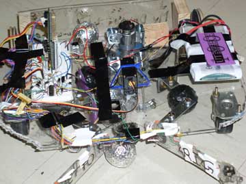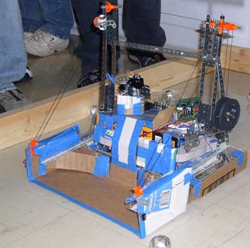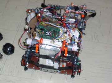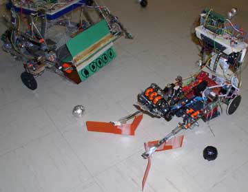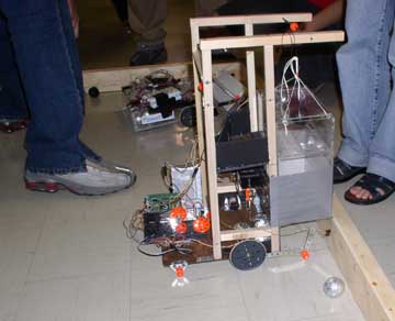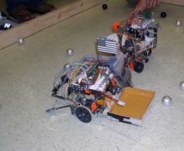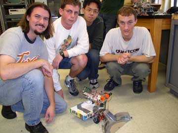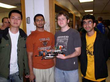
Lab 27 The Scooper/Sorter  Robot (Fall 2003) See winners
The robot materials were funded by a grant from Tivioli.
Home page
Ideas for EE345M Fall 2004 (send
your thoughts to my email at Jonathan
W. Valvano):
1) line-tracker road
rally: follow a figure 8 track at a constant speed
2) two
wheel bicycle
3)
parallel parking robot
Goals	o Design a robot that can move forward/backward, turn left/right, and pick/sort balls
	o Interface motors and sensors to the 6812,
	o Implement pulse-width modulation,
	o Write low-level device drivers for the motors and sensors,
	o Develop a high-level control system,
	o Use communication skills to work effectively as team.

Review	o Chapter 8 on interfacing DC and stepper motors to the MC68HC812A4,
	o Chapter 6 on pulse-width measurement and input capture,
	o Chapter 2 on finite state machines,
	o Chapter 13 on control systems,
	o Construction guide for the erector set,
	o Data sheets for 74HC14, IRF522, IRF540, L293, and TIP120.

Starter files	o PWMOD.C, OC3.C, FSM12.C, FuzMotor.C, LCD12.C, MOORE12.C, MOORE2.C
Background
	The overall goal is to search the playing field for the aluminum-covered golf balls, pick them up and hold them somewhere within the robot. Four walls enclose the field containing about 30 aluminum-covered golf balls and 10 black-taped golf balls. Two robots will begin at the same time with their backs touching opposite sides. The two robots have 3 minutes to collect as many aluminum-covered balls as possible (+10 points each) without collecting any of the black ones (-20 points each).  The balls must be lifted off the ground (not just squatted over like a duck), and there are no penalty points for temporarily picking up a black ball, as long as it not being held at the end of the 3 minutes. Points are scored at the end of the 3 minute contest by counting the balls held off the ground within the robot. The walls are constructed from four 6-foot long 2" by 4" boards, which are actually about 8 cm high. All robots must behave like proper ladies and gentlemen, i.e., you are not allowed to purposefully damage or disable the other contestant. The maximum footprint of the robot is 16 by 16 inches, but there are no height or weight limits. You are allowed to use additional passive materials not contained in the kit (e.g., wheels, gears, string, wood, metal, plastic, wire, tape), but you are restricted to the active components (motors, servos, sensors) from the kit. You are allowed to check out additional quantities of the same type of component (while supplies last). If you can't get the battery power to work, you can compete in the tethered-power division.
Wednesday, December 3, 1-2pm:  in the lobby of ENS
Each robot kit contains the following materials, donated by Tivioli
Amazon.com,  Erector Special Edition Anniversary Set, 643 pieces, $99.99 each
	Case, DC motor, wheels, axles, drive belts, pulleys, large and small metal pieces, many nuts and bolts
BG Micro, bgmicro.com,
	Quantity 1, BAT1060, 8.4V/3.8AH, NiMH battery, $7 each
	Quantity 1, PWR1123, 5VDC/4A Switcher power supply, $6.49 each
	Quantity 1, PWR1020, Computer Power Cord, $1.19 each
All Electronics Corporation, Phone 1-800-826-5432
	Quantity 4, SPR-5, 0.19"D by 0.3" L SPRING, O.L.0.7", $0.06 each
	Quantity 4, SMS-189, MINI-SNAP-ACTION SWITCH, $0.50 each
Jameco, 1-800-831-4242, www.jameco.com
	Quantity 1, 12VDC unregulated, NiMH charger, $5 each
	Quantity 1, 162190, HNGH12-1324Y MOTOR GEAR 225RPM 12VDC, $10.95 each
		12V (but will work at 5V or 8.4V), 65 mA, 225 RPM at 12V, torque 700g-cm, shaft diameter 0.16in
	Quantity 2, 163395, 5017-935, 30 ohm, 280 mA, 400 steps/rotation stepper motor, $3.19 each
		8.4V (but will work at 5V), detent torque 36g-cm, holding torque 791g-cm, shaft diameter 0.155in
	Quantity 1, 157067, 14500 RBT SERVO MOTOR & GEAR, $17.95 each
		4.8 to 6V, torque 49 oz-in, speed 16 seconds to 60 degrees
		don't run this at 8.4, but rather through the Adapt 5V regulator
	Quantity 100, 42446, 6-32 STD machine screw, $0.016 each
	Quantity 100, 42420, 6-32 STD hex nut, $0.012 each
	Quantity 100, 106868, #6 lock washer, $0.012 each
Mouser Electronics
	Quantity 2, QRB1134, optical reflective object sensor, $2.00 each
Other materials available for checkout in ENS627 include
	PWR1109, 6VDC/1A Power supply, $2.95 each (from BG Micro)
	AIRPAXC42MO48A04 MOTOR STEP 5VDC/9.1ohm, $2.36 each  (from Jameco)
	SPR-3, 0.4" DIA. by 3.65" SPRING, $0.15 each (from All Electronics)
Electronics available for checkout on the second floor
	IRF522, N CHANNEL MOSFET, drives up to 8A, $0.40 each
	TIP120, NPN TO-220 DARLINGTON, $0.65 each
	1N4004, RECT DIODE 1AMP/400PIV, $0.09 each
	L293B, H-bridge driver, $1.15 each
27A. Preparation (this is due by 1 pm Friday November 7 and turn it in to any TA)
1: Create a robot design team with 4 to 5 members. If you create a team with more than 5 members, you will be asked to solve the problem using two 6812's. The members do not have to be in the same lab section or have the same TA as the previous labs. The ideal team has at least one member with strengths in the areas of mechanical design (e.g., pulleys, belts, motors, and rack-and-pinion steering), electrical interfacing (e.g., transistors, currents, back EMF, servo interfacing, and sensor interfacing), power management (e.g., maintaining constant +5V power to the 6812 while operating the motors), software design (e.g., device drivers, juggling multiple time-critical tasks, making it fit into 4K of ROM space), high-level control, and project management (e.g., conflict resolution, report generation, and keeping on schedule). Part of your final project grade will be confidential peer evaluations, so choose your team wisely, then make a commitment to get this project finished. Please turn in the following:
	first and last names of all team members
	home phone numbers of all team members
	email addresses of all team members
	select at least two times each week for an official team project meeting (without the TA)
	list all the regularly scheduled lab hours that it is possible for all your members to meet weekly with a TA
		We will select one of these hours to be when your preparation and demonstrations will be due.
27A. Procedure (do this during your lab period)
1: Design and build the mechanical aspects of the robot. It must move, turn, carry the electronics, and recognize a collision. Make a rough mechanical sketch of the robot showing how it moves, turns, carries, and senses. A detailed drawing will be required for the final report, but at this time only a rough sketch is required. I.e., just enough detail for the TA to understand your basic approach, but not enough detail for someone to build a duplicate.
2: Design the electronic interface between the steering and power motor(s) and the 6812. We expect you to use the 8.4V NiMH battery, but if that fails you may use the 4A +5V regulated supply to power the system. Please test the circuitry before connecting to the 6812. Snubber diodes must be used for all devices having an inductive load. Please consider the required current when designing the interfaces. Use a multimeter to measure the actual voltages and currents across the motors. Watch the +5V signal on the scope during times when motors are turned on and off to verify a constant +5V power supply line to the 6812. Please thoroughly test all interfaces before connecting to the 6812.
3: Show how the system will be powered.
4: Design the low-level software drivers for the movement and steering motors.
5: Design the low-level software drivers for the detection of collisions.
6: Write a simple high-level main program to test the movement, steering and collision detection. Measure the maximum speed of the robot. Experimentally determine the best way to make turns. Calculate the accuracy of the turning algorithm. I.e., if you say turn +90, how many degrees does it actually turn?
7. Debugging a complex system like this is very hard. Please design features into the robot to assist in debugging.
27A. Deliverables (exact components of the lab report)
A) Objectives (not required for this 27A)
B) Hardware Design
	1) Rough mechanical sketch of the robot (Section 1)
	2) Electrical circuit diagram for the motor interfaces (Section 2)
	3) Power supply circuitry  (Section 3)
C) Software Design (printout of these software components)
	1) Low-level device drivers for the motor interfaces (header and code files) (Section 4)
	2) Low-level device drivers for collision detection (header and code files) (Section 5)
	3) High-level test program to evaluate movement, steering and collision detection (Section 6)
D) Measurement Data
	1) Give the voltage and currents of each of the motors used (Section 2)
	2) Give the robot speed and turning accuracy (Section 5)
E) Analysis and Discussion
	1) Minutes (date, time, duration, attendance, topics) for each team meeting
27A. Checkout (show this to the TA)
	You should be able to demonstrate to the TA your robot moving forward, backward, and turning. You should demonstrate the detection of collision. Explain your debugging features you have built into the device.

27B. Preparation (do this before your lab period)
1: Develop a high-level plan of how your robot will traverse the field collecting shiny balls.  Your algorithm must involve abstractive methods. I.e., it must be layered, with a high-level algorithm separated from the low-level details of how the machine operates. A finite state machine like moore2.c is one example of how this abstraction might be implemented. You are of course allowed to develop your own approach, as long as there is a clear mapping from the high-level algorithm to the eventual C code. For example, if you decide to implement a finite state machine, write the state graph for the scooper/sorter algorithm.
2: Develop an initial data flow graph of the hardware-software system. Include the motors, sensors, interface drivers, interrupt service routines, and strategic global variables.
3: Develop an initial call graph of the software system. Include foreground and background modules and their linkage (which ones call which).
4: Write the header file for the low-level sensor software driver.
27B. Procedure (do this during your lab period)
1: Design the electronic interfaces connecting the optical sensors to the 6812. Again, please test the circuitry before connecting to the 6812.
2: Design the low-level software drivers for the scooping and sorting of balls, using information from the optical sensors.
3: Write a second high-level main program to test the movement, steering and sensors. This program should demonstrate most of the middle-level building blocks that will be required for the high-level scooper/sorter algorithm. Monitor the power supply current during various operations (stopped, moving and turning).
4. Experimentally verify the robot can determine which ball it has scooped.
27B. Deliverables (exact components of the lab report)
A) Objectives (not required for this 27B)
B) Hardware Design
	1) Most recent electrical circuit diagram for the motor interfaces (27A Section 2)
	2) Most recent power supply circuitry  (27A Section 3)
	3) Electrical circuit diagram for the sensor interfaces (27B Section 1)
C) Software Design (printout of these software components)
	1) Low-level device drivers for the motor interfaces (header and code files) (27A Section 4)
	2) Low-level device drivers for the scooper/sorter interfaces (header and code files) (27B Section 2)
	3) High-level test program to evaluate movement, steering and sensing (27B Section 3)
D) Measurement Data
	1) Power supply current for various operations (27B Section 3).
	2) Accuracy of the object detection system (27B Section 4)
E) Analysis and Discussion
	1) Minutes (date, time, duration, attendance, topics) for each team meeting
	2) List of the remaining major problems to solve
27B. Checkout (show this to the TA)
	You should be able to demonstrate to the TA your robot can scoop and sort golf balls. Explain how you tested.

27C. Preparation (do this before your lab period)
1: Write the C code for the scooper/sorter algorithm using abstractive methods. It should have a clear mapping from the high-level algorithm to the C code.
2: Make detailed mechanical drawings of the robot showing how it moves, turns, carries, and senses. There should be enough detail so the robot could be duplicated.
27C. Procedure (do this during your lab period)
1: Debug the high-level scooper/sorter algorithm.
2: Draw the final data flow graph of the hardware-software system. Include the motors, sensors, interface drivers, interrupt service routines, and strategic global variables.
3: Draw the final call graph of the software system.
4. Run the robot al least five times and measure the score during the 3-minute solo trials.
27C. Deliverables (exact components of the lab report)
A) Objectives (1/2 page maximum)
B) Hardware Design
	1) Final mechanical drawing of the robot (27C preparation)
	2) Final electrical circuit diagram for the motor interfaces (27A Section 2)
	3) Final power supply circuitry  (27A Section 3)
	4) Final electrical circuit diagram for the sensor interfaces (27B Section 1)
C) Software Design (printout of these software components)
	1) Low-level device drivers for the motor interfaces (header and code files) (27A Section 4)
	2) Low-level device drivers for the sensor interfaces (header and code files) (27B Section 2)
	3) High-level algorithm to scoop and sort the balls (27C Section 2)
	4) Final data flow graph
	5) Final call graph
D) Measurement Data
	1) Scores during 3 minute solo trials
E) Analysis and Discussion (1 page maximum)
F) Post-mortem concerning team member interactions (attached to the report)
	1) Each team member evaluates each other team member including oneself
		Simply list one or two weaknesses.
Simply list two or three strength characteristics.
	2) Major failures in the way the team interacted (if any)
	3) Major successes in the way the team interacted
G) Peer Review (each student submits independently and confidentially directly to the TA)
	Classify each team member including oneself as:
	 - worked harder than average (explain),  worked an average amount,  worked less than average (explain)
27C. Checkout (show this to the whole class on demo day)
	You should compete in the class demonstration/competition on Wednesday December 3.
Home page