One of the simplest beamforming systems is called the weighted delay-and-sum beamformer.
Weighted Delay-and-Sum Beamformer
In this method, the beamformer output b(t) is formed by summing weighted and delayed versions of the receiver signals. The weight is given by wi, and the delay is ti.

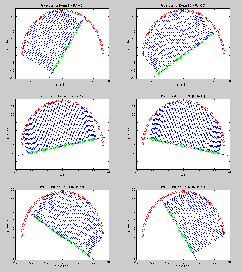
The delay used for each sensor element is determined by array geometry and the desired pointing direction. To steer the beam in the direction ao, the delays should be set to ti = -ao'xi. In two dimensions, we project the elements onto a line which is perpendicular to the beam's desired pointing direction, which gives a distance for each element. This distance (divided by the speed of sound) gives the delay required to steer the beam in the desired direction.

Array Pattern
Like any filter, a beamformer is not ideal -- the array pattern indicates the response of the array. It is given by the following equation:

The array pattern is essentially the Fourier transform of the receiver weighting function wi, taking into account the positions xi of the receivers. The function W(k-ko) indicates the attenuation of a plane wave propagating in the direction a when the beamformer is steered in the direction ao.
For the special case where all the components of a wideband signal are propagating in the same direction, and the signal crosses the array in the beamformer's steering direction, the beamformer does not distort the waveform. Signals which are not aligned suffer a distortion similar to lowpass filtering.
The classic simple example is that of a linear array of N elements, uniformly spaced D units apart (placing the array on the x-axis). For omnidirectional elements, and all elements weighted 1/N, the response is (D=1, N=15):

The beamwidth, which is the width of the main lobe, is inversely proportional to the product ND. This product can be thought of as the length of the array aperture.
Notice that the array pattern is periodic in kx, with a period of 2p / D. These repeated mainlobes are called grating lobes, analogous to the higher diffraction orders caused by an optical diffraction grating. These can be interpreted as spatial frequency aliasing from a spatial sampling interval D which is too large. This aliasing can occur unless D <= l / 2. To prevent this from happening, the receiver signals may be lowpass filtered to eliminate the high-frequency signal components that may be passed by grating lobes.
The Receiver Weighting Function
Also notice that the response is similar to sinc( NDkx/ 2p). It is, in fact, the frequency response of a 1-D comb filter of length N. This demonstrates the effect of the receiver weighting (also called shading) on the shape of the array pattern -- it is equivalent to window functions in DSP. In selection of the weights, the usual tradeoffs are made between the width of the main lobe and the height of the side lobes.
The problem of designing the weights for an arbitrary array geometry is analogous to that of designing a multidimensional FIR filter whose impulse response consists of unequally spaced nonzero samples.
Sensor Element Responses
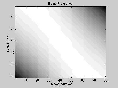
The above discussion is only for sensor elements which are omnidirectional. In general, this is not the case. Note that in the above projection with the curved array, we did not use every sensor to calculate every beam. Since our array is curved, each sensor contributes to each beam differently. In the following plot, high responses are white and low responses are black. If the element and the beam point in the same direction, the response is high.

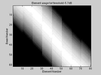
It doesn't make sense to use elements which point in the wrong direction. In the following plot, any element which is some fixed threshold below its maximum is zeroed out. Now we're only using the nonzero elements to form each beam. Although the remaining elements could be used in the calculation, their response in the direction of interest is relatively small for this geometry, and they would merely add noise. Leaving these elements out would also substantially reduce computation.

Filter-and-Sum Beamforming
Filter-and-sum beamforming is simply more generalized, where the receiver weighting function depends on frequency. For each sensor in the array, we filter the output ri(t) with a weighting function wi(t) to yield a filtered signal qi(t).
Then we perform our same delay-and-sum operation on the filtered signal. (The weights are already included in the signal).

Again, the delays should be set to ti = -ao'xi to steer the beam in the direction ao.
Frequency-Domain Beamforming
Beamforming can also be performed in the frequency domain, where delaying the signal ri(t) by ti is implemented by multiplying Ri(w) by the phasor exp(-jwti). However, we do not have access to the entire spectrum Ri(w). Instead, we transform a segment of ri(t) by applying a finite extent window and computing the short-time Fourier transform Ri(t,w), an approximation to Ri(w). Now the frequency-domain beamformer output is:

Note that the frequency-domain beamformer is inherently narrowband. The exp(-jwti) term performs the time delay, and the exp(jwt) term extracts the component of the beamformer output b(t) at the frequency w. An approximation to b(t) could be formed by integrating fd(t,w) over frequency.