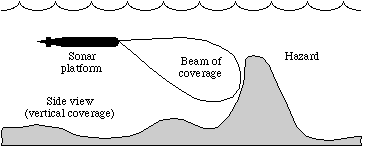
Sonar, the acoustic analog to radar, is a method for detecting and locating objects using acoustic waves. It is often employed in environments where acoustic wave propagation is superior to electromagnetic wave propagation, such as under water. Sonar can be used for navigation, to identify hazardous or hostile objects, and to map terrain features in the surrounding environment.

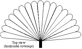
High-resolution sonars generally consist of an array of underwater sensors along with a beamformer to determine from which direction a sound is coming. The higher the resolution of a sonar system, the more accurately the location of an object can be determined. To achieve high resolution over a wide coverage area, a large number of beams may be formed. This figure illustrates a high resolution, multi-beam sonar with several narrow horizontal beams covering a wide horizontal sector.

The sensor element outputs must be combined to form these multiple narrow beams, each of which "looks" in a single direction and is insensitive to sound in neighboring directions. This combination must be performed with precise time delays and amplitude weighting applied to the sensor outputs. As a result, beamforming for high-resolution sonar systems is extremely computationally intensive.
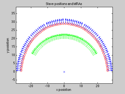
A beamformer is a spatial filter that operates on the output of an array of sensors in order to enhance the amplitude of a coherent wavefront relative to background noise and directional interference. The figure below shows a curved array of hydrophone sensors, or staves. Each sensor (red circle) is located at an (x,y) coordinate as shown. These sensors are pointed in known directions (blue arrows), and we wish to form beams which point in chosen directions (green arrows). The "pointing direction" is called the Maximum Response Angle (MRA), and can be arbitrarily chosen for the beams.

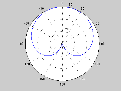
The response of a given element is plotted on a polar graph, where the angle is the offset from the MRA, and the radius is the magnitude response (dB) in that direction. Element responses (determined by the 3dB down point) are very wide -- in this example the width is about 90 degrees.

The goal of beamforming is to sum multiple elements to achieve a narrower response in a desired direction (the MRA). That way when we hear a sound in a given beam, we know which direction it came from.The beamwidth is the 3dB width of the main lobe. The sidelobe level is the level of the first sidelobe. A null is the region of low response between lobes.