Fall 2008: EE 382N-4 Unique: 17228a
Advanced Embedded Systems Architecture
Lab Assignment #2: Due Dec 7th, 2008
AIM: Measure the interrupt latency of iMX21 Board.
Specification:
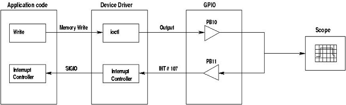
The functional diagram of
the required setup is shown in the block diagram below.
1) GPIO pin PB11 will be used as an
interrupt pin (rising edge sensitive interrupt) and GPIO pin PB10 will be used
to drive the interrupt pin in a loopback.
2) The application code should
trigger the interrupt by asserting the PB10 pin.
3) The resulting interrupt (interrupt
# 107) should be handled in an interrupt handler in the application code. Code
in the application interrupt handler de-asserts the PB10 pin.
4) The interrupt latency (time delay
between the assertion of PB10 in the application code and the execution of the
interrupt handler) should be measured within the application code. This
measurement should be performed 10 times and the average, minimum, and maximum
latencies should be reported.
5) The interrupt latency (time delay
between the assertion of the PB10 pin and its de-assertion) should also be measured
using a scope probing the PB10 pin.
6) Teams of 4 members.
7) Each team needs to demonstrate the
code
Implementation details:
1) Modify the mx21_gpio device driver
code to do the following:
a. Configure the Port B Pin 11 as an
input interrupt pin the Port B Pin 10 as an output pin.
b. Request interrupt # 107 to be
handled by an interrupt handler routine in the device driver. The interrupt
should be requested to be rising edge sensitive.
c. Notify the application code about
the occurrence of the interrupt using the
kill_fasync routine (inside the interrupt handler).
2) Write a user application code
which does the following:
a. Trigger the interrupt by opening
the /dev/gpio and writing to the appropriate address to assert PB10.
b. Handle the SIGIO from the device
driver in an interrupt handler. The interrupt handler should de-assert PB10
pin.
c. Measure the time difference
between the assertion of PB10 pin and the execution of the interrupt handler.
Useful links:
a)
fpga_int.c
is a device driver which registers interrupt
# 240 for itself and flags the user application in the event of an interrupt. mon_int.c is the user application code which interfaces with the
fpga_int device driver. This user application code keeps a count of the number
of interrupts that occurred.
b)
mx21_gpio.c:
The base device driver which you can modify
for the purpose of this lab.
c)
Example
interrupt latency measurement codes for different boards. These are device drivers written to measure interrupt latency
on various boards and hence the method of configuring various registers is
different in these drivers. In these drivers, an interrupt is asserted when the
/proc/interrupt_latency file is read. The interrupt handler within the device
driver de-asserts the interrupt pin. The interrupt is not passed on to the user
application in these drivers.
d)
The MX21 board
documentation at /scratch/Documentation/MC9328MX21RM.pdf. Chapter 15 contains a
note about the GPIOs. The configuration details of the GPIO registers are given
here.