As mentioned in class, the finite state machine has some race conditions. Identify the race conditions and show what simple modifications can be made to eliminate them.
Every time a disk unit finishes a transfer, the LC-3b is interrupted, and the disk unit is given another transfer operation. The unit of transfer between the disk and the memory is a 212 B page and the disk units are capable of maintaining a transfer rate of 218 B/s. The bus itself is the fastest technology and is able to keep up with the transfer rate of the disk units (i.e., the bus does not slow down the transfer between disk and memory).
After a few experiments, the students found that the average disk transfer consisted of 2 pages of data. The disk interrupt handler on the LC-3b was known to take 5 ms of processing time per interrupt. The goal of their experiment was to figure out how many disk units could be connected to the system and fully utilized. Help them out.
MUL R3, R1, R2
ADD R5, R4, R3
ADD R6, R4, R1
MUL R7, R8, R9
ADD R4, R3, R7
MUL R10, R5, R6
Note: Each instruction is specified with the destination register first.
Calculate the number of cycles it takes to execute the given code on the following models:
- A non-pipelined machine.
- A pipelined machine with scoreboarding with one multiplier and one adder.
- Tomasulo's algorithm with one multiplier and one adder.
Show the state of the reservation stations (node tables) and the register file (with the valid bits and the tags) for part (3) after 5 clock cycles. Show it after 10 clock cycles. Assume that the adder and the multiplier both have 4 entries in their associated reservation stations. Use symbolic tags for renaming as Professor Patt did in class. The structure of the reservation stations and register file (register alias table) should be the same as explained in lecture.
Note: For all machine models, use the basic instruction cycle as follows:
-
Fetch (one clock cycle)
Decode (one clock cycle)
Execute (MUL takes 4, ADD takes 2 clock cycles)
Write-back (one clock cycle)
Do not forget to list any assumptions you make about the pipeline structure (e.g., data forwarding between pipeline stages).
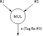
Draw the dataflow graph for the code we used in lecture to describe Tomasulo's algorithm. Label the nodes with the opcodes of the instructions and the arcs with the tags. The program and the first node of the data flow graph are shown below.
   MUL  R3, R1, R2
   ADD  R5, R3, R4
   ADD  R7, R2, R6
   ADD  R10, R8, R9
   MUL  R11, R10, R7
   ADD  R5, R11, R5
For this problem assume stores take 11 cycles, shifts take 1 cycle and loading the vector length and vector stride registers each take 1 cycle.
Given the following code segment:
for(i = 0; i < 100; i++)
  A[i] = (B[i] * C[i] + D[i]) / 2;
Write Cray-like assembly code to perform the calculation. Then compute the number of cycles required for the code segment to execute on the following machines:
- Scalar processor
- Vector processor without chaining, 1 port to memory (1 load or store / cycle)
- Vector processor with chaining, 1 port to memory
- Vector processor with chaining, 2 read ports and 1 write port to memory
Show what the pipeline looks like and how the following code gets executed for four cases (based on taken, not-taken result of the conditional branch instructions).
            A
            B
            C
	    BC X
	    BC Y
	    D
	    E
	    F
	    G
	X   H
	Y   I
	    J
DOIT     STW   R1, R6, #0
         ADD   R6, R6, #1
         AND   R3, R1, R2
         BRz   EVEN
         ADD   R1, R1, #3
         ADD   R5, R5, #-1
         BRp   DOIT
EVEN     ADD   R1, R1, #1
         ADD   R7, R7, #-1
         BRp   DOIT
Assume that before the loop starts, the registers are initialized to the following integer values:
R1 <- 0
R2 <- 1
R5 <- 5
R6 <- 4000
R7 <- 5
"Fetch" takes 1 cycle, "Decode" takes 1 cycle, "Execute" stage takes
variable number of cycles depending on the type of instruction (see below), and "Store Result" stage takes
1 cycle.
All execution units (including the load/store unit) are fully pipelined and the following instructions that
use these units take the indicated number of cycles:
STW: 3 cycles
ADD: 3 cycles
AND: 2 cycles
BR : 1 cycle
For example, the execution of an ADD instruction followed by a BR would look like:
ADD       F | D | E1 | E2 | E3 | ST
BR            F | D  | -  | -  | E1  | ST
TARGET                                 F  | D
This figure shows several things about the structure of the pipeline:
- Whenever possible, data forwarding is used. Instructions that are dependent on the previous instructions can make use of the results produced before right after the previous instruction finishes the "Execute" stage.
- Branch instructions require 1 "execute" cycle to resolve the branch. Hence, the target instruction can be fetched when the BR instruction is in ST stage.
Also, you are given the following information about the pipeline and the ISA:
- The pipeline implements "in-order execution". A scoreboarding scheme is used as discussed in class.
- The pipeline emulates the LC-3b ISA. Hence, the above instructions are all LC-3b instructions.
Answer the following questions:
a) How many cycles does the loop above take to execute if no branch prediction is used?
b) Suppose that a static BTFN (backward taken-forward not taken) branch prediction scheme is used to predict branches.
i. How many cycles does the above loop take to execute with this scheme?
ii. What is the branch prediction accuracy?
iii. What is the prediction accuracy for each branch?
c) Suppose that two-bit saturating up/down counters (as discussed in lecture) are used for branch prediction. Each branch instruction has its own counter. The counters are initialized to '10' state. Top bit of the counter is used as the prediction. Hence, the first time a branch is seen it will be predicted taken.
i. How many cycles does the above loop take to execute if two-bit counters are used for branch prediction?
ii. What is the branch prediction accuracy?
iii. What is the prediction accuracy for each branch?
Signed decimal numbers consisting of n digits can be represented in n + 1 digits without a sign. Positive numbers have 0 as the leftmost digit. Negative numbers are formed by subtracting each digit from 9. Thus the negative of 014725 is 985274. Such numbers are called nine's complement numbers and are analogous to one's complement binary numbers. Express the following as three-digit nine's complement numbers: 6, -2, 100, -14, -1, 0.
From Tanenbaum, 4th edition, Appendix B, 4.
The following binary floating-point number consists of a sign bit, an excess 63, radix 2 exponent, and a 16-bit fraction. Express the value of this number as a decimal number.
0 0111111 0000001111111111
From Tanenbaum, 4th edition, Appendix B, 5.
To add two floating point numbers, you must adjust the exponents (by shifting the fraction) to make them the same. Then you can add the fractions and normalize the result, if need be. Add the single precision IEEE floating-point numbers 3EE00000H and 3D800000H and express the normalized result in hexadecimal. ['H' is a notation indicating these numbers are in hexadecimal]
From Tanenbaum, 4th edition, Appendix B, 6.
The Tightwad Computer Company has decided to come out with a machine having 16-bit floating-point numbers. The model 0.001 has a floating-point format with a sign bit, 7-bit, excess 63 exponent and 8-bit fraction. Model 0.002 has a sign bit, 5-bit, excess 15 exponent and a 10-bit fraction. Both use radix 2 exponentiation. What are the smallest and largest positive normalized numbers on both models? About how many decimal digits of precision does each have? Would you buy either one?
x4000: Low 16 bits of first integer
x4002: High 16 bits of first integer
x4004: Low 16 bits of second integer
x4006: High 16 bits of second integer
x4008: Low 16 bits of the result
x400A: High 16 bits of the result
How many cycles does your program take to execute if the 32-bit integer at location x4000 is xFFFFFFFF and the 32-bit integer at location x4004 is x00000001?
a. A 1-bit carry condition code (C). This condition code is set to 1 if the ADD operation generates a carry-out.
b. A new instruction in the instruction set:ADDC DR, SR1, SR2/imm5which adds the contents of SR1 and SR2/imm5 together with the carry condition code to generate the sum in DR. ADDC instruction also sets the C condition code.
How many cycles does your program take to execute if the 32-bit integer at location x4000 is xFFFFFFFF and the 32-bit integer at location x4004 is x00000001? Assume that ADDC instruction takes the same number of cycles as the ADD instruction to execute.