Chapter 4. Internet of Things
Table of Contents:
- 4.1. Basic Concepts
- 4.2. Layered Models
- 4.3. Message Protocols
- 4.4. Client Server
- 4.5. Web server
- 4.6. UDP
- 4.7. TCP
- 4.8. If-this-then-that
- 4.9. Blynk
- 4.10. MQTT
- 4.11. Lab 4
"The Internet of Things (IoT) is the network of
physical devices, vehicles, home appliances, and other items embedded with
electronic, software, sensors, actuators and connectivity which enables these
things to connect and exchange data, creating opportunities for more direct
integration of the physical world into computer-based systems, resulting in
efficiency improvements, economic benefits, and reduced human exertions." -
Wikipedia
4.1. Basic Concepts
4.1.1. Internet of Things
With the proliferation of embedded systems and the pervasiveness of the internet, it is only natural to connect the two. The internet of things (IoT) is the combination of embedded systems, which have sensors to collect data and actuators to affect the surroundings, and the internet, which provides for ubiquitous remote and secure communication. This section will not describe how the internet works, but rather we will discuss both the general and specific approaches for connecting embedded systems to the internet. For an excellent description of the TCP/IP (Transmission Control Protocol/Internet Protocol) protocol the reader is referred to W. Richard Stevens, TCP/IP Illustrated, Volume 1: The Protocols. For a general description of the internet of things, see Vasseur and Dunkels, Interconnecting Smart Objects with IP.
Figure 4.1.1 illustrates the distributed approach taken with the internet of things. A distributed solution deploys multiple sensors and actuators connected by the internet. Many names are given to embedded systems connected to the internet:
Internet of things
Smart object
Edge computing
M2M (Machine to Machine)
"Internet of Everything" IoE (Cisco Systems)
"World Size Web" (Bruce Schneier)
"Skynet"
Smart objects include sensors to collect data, processing to detect events and make decisions, and actuators to manipulate the local environment. There are many reasons to consider a distributed solution (network) over a centralized solution. Often multiple simple microcontrollers can provide a higher performance at lower cost compared to one computer powerful enough to run the entire system. Some embedded applications require input/output activities that are physically distributed. For real-time operation there may not be enough time to allow communication between a remote sensor and a central computer. Another advantage of distributed system is improved debugging. For example, we could use one node in a network to monitor and debug the others. Often, we do not know the level of complexity of our problem at design time. Similarly, over time the complexity may increase or decrease. A distributed system can often be deployed that can be scaled. For example, as the complexity increases more nodes can be added, and if the complexity were to decrease nodes could be removed. Table 4.1.1 lists some existing applications and the things they sense or control.
Figure 4.1.1. The internet of things places input, output and processing at multiple locations connected over the internet.
Industrial Automation Factories, machines, shipping
Environment Weather, pollution, public safety
Smart Grid Electric power, energy delivery
Smart Cities Transportation, hazards, public services
Social Networks Ideas, politics, sales, and communication
Home Networks Lighting, heat, security, information
Building Networks Energy, hazards, security, maintenance
Structural Monitors Bridges, roads, building
Health Care Heart function, medical data, remote care
Law enforcement Crime, public safety
Table 4.1.1. Applications of smart objects.
Challenges. On a local scale, the design of smart objects faces the same challenges existing in all embedded systems: power, size, reliability, longevity, and cost. Luckily the deployment of billions of microcontrollers into the market has created a technological race to reduce power, size and cost while increasing performance. At the microcontroller level things are getting smaller, but at the network level, complexity is increasing, and protocols are constantly changing as the world's thirst for information and communication rapidly grows.
Standardization. The existence of standards allows for a wide variety of objects to communicate with each other. Adhering to a standard will increase the acceptance of our device by customers and allow our customers to apply our device to solve problems we never envisioned. uIP is a light-weight implementation of the IP stack specifically designed to operate with the available memory resources of smart objects. In this section we will start with a microcontroller with the hardware and software to implement TCP/IP protocols and build our application on top of this standard.
Interoperability means our device can function with a wide range of other devices made with different technologies, sold by different vendors, and produced by different companies.
Evolution is a process of how new technologies are introduced into the market. If there is one constant in this world, it is that things will change. Every thousand years, one big discovery fundamentally changes how we operate (fire, language, metal tools). More frequently, change is introduced gradually such that those technologies that give us a competitive advantage survive. If we build our business model on the premise evolutionary change, then we can be nimble to deploy new technology when it provides lower cost and/or better performance.
Stability. Even though technology will advance, our customers demand products that work reliably, for a long time, and in a manner with which they are comfortable. Over the last 50 years automotive technology has drastically improved, but the driving experience, how we drive, has remained almost constant.
Abstraction. You will notice the approach in this section differs widely from the other examples in this book. The rest of the book deploys a bottom-up approach. With bottom-up education, the details are first explained, so there is no magic, and then abstraction occurs by encapsulating that we fully understand. In this section we will purchase hardware and software with capabilities to communicate with the internet and use this abstraction without fully understanding how some of the lower levels operate.
Scalability. ARM reports that over 160 billion devices with an ARM core have been shipped as of 2020. To be effective and profitable, we need to develop systems that can scale.
Security. Because embedded systems are deployed in life-critical situations, and because the quality of service affects our profits, we must protect the system from a determined adversary. A chain is only as strong as its weakest link. Security cannot be obtained simply by operating in secret, because once the secret is out, the system will be extremely vulnerable. "Security by obscurity" is a very poor design method. Security involves more than encrypting the data. The first aspect of security is confidentiality. We must decide what it means to view/change the data and who has the right to read/write. Authentication is the means to ensure the identity of the sender is correct. Confidentiality will require both logical and physical measures to protect against an attack. Encryption makes it harder for an unauthorized party to view a message. The second aspect is data integrity. For most of the applications listed in Table 4.1.1 it is important that data reach the rightful recipient in an unaltered fashion. To support network integrity, we need techniques that support both detection and prevention. The third aspect is availability. Secure communication not only requires the correct data to arrive at the correct place, but also at the correct time. A Denial of Service (DoS) attack attempts to breach the availability of the network. For wired networks, we can reroute traffic along multiple paths. With wireless networks, we can channel hop by switching channels on a pseudorandom fashion, making it harder for an attacker to jam. For more information on security, see Frank Stajano, Security for Ubiquitous Computing.
IoT is all about Cognitive Transducers, see Figure 4.1.2.
Measure something with sensors
Communicate with other devices
Do it again - reliably
Perception about the environment
Reason and make decisions (AI on the edge)
Control something with actuators
Figure 4.1.2. What makes an IoT special are its sensors and actuators.
Cognition in the context of a sensor platform is defined as the "process of knowing, including aspects of awareness, perception, reasoning, and judgment". The hierarchy of capabilities of a cognitive sensor include:
Self-knowledge - the sensor identifies its purpose and understands its operational functions.
Perception - the sensor can recognize, interpret, and understand sensor data.
Reasoning - the sensor can make decisions based on perception of sensor data.
Cognition - the sensor has knowledge, perception, reasoning.
Communication - the sensor can transmit/receive processed information to/from other devices
IoT devices have many vulnerabilities (from https://www.utdallas.edu/infosecurity/)
Default, weak, and hardcoded credentials
Difficult to update firmware and OS
Lack of vendor support for repairing vulnerabilities
Vulnerable web interfaces (SQL injection, XSS cross-site scripting)
Coding errors (e.g., buffer overflow)
Clear text protocols and unnecessary open ports
Denial of Service (DoS), Distributed denial-of-service (DDoS)
Physical theft and tampering
4.1.2. Network Topology
Consider three topologies in Figure 4.1.3. The Gateway node is the bridge to the internet. A sensor node can be simple or have routing capabilities. A point-to-point network has just two nodes, which are connected to each other. It is simple and private. A star network has one central node, and all the other nodes are connected to the central node. All routing paths go through the central node. The star is simple, low cost, and easy to configure. A mesh network has redundant connections, and multiple routing paths. The mesh is robust in the face if node failure, dynamically reconfigurable, and suitable for mobile applications.
Figure 4.1.3. Network topologies.
: A sensor node sends a message to another sensor node in a star. Could multiple copies of the message arrive at the destination?
: A sensor node sends a message to another sensor node in a mesh. Could multiple copies of the message arrive at the destination?
4.1.3. Modulation
We will study communication systems in more detail in Chapter 9, but Figure 4.1.4 shows three modulation techniques. wifi uses a combination of amplitude-shift and phase-shift keying. RF waves are sent from tranmission antenna and received by an antenna in the receiver. Amplitude shift key encodes the data as amplitudes of the RF signal. Frequency shift key encodes the data as two or more frequencies of the RF signal. Phase shift key encodes the data as phase shifts in the RF signal. For details on the wireless protocol, see Lea, IoT and Edge Computing for Architects
Figure 4.1.4. Three modulation techniques (IoT and Edge Computing for Architects, Lea).
: Which of the above modulation techniques could we use with sound as the communication medium?
: What physical entity is sent from transmitter to receiver?
4.2. Layered Model
4.2.1. Open Systems Interconnect (OSI)
Most networks provide an abstraction that hides low-level details from high-level operations. This abstraction is often described as layers. The International Standards Organization (ISO) defines a 7-layer model called the Open Systems Interconnection (OSI), as shown on the left of Figure 4.2.1. It provides a standard way to classify network components and operations. The Physical layer includes connectors, bit formats, and a means to transfer energy. Examples include RS232, controller area network (CAN), modem V.35, T1, 10BASE-T, 100BASE-TX, DSL, and 802.11a/b/g/n PHY. The Data link layer includes error detection and control across a single link (single hop). Examples include 802.3 (Ethernet), 802.11a/b/g/n MAC/LLC, PPP, and Token Ring. The Network layer defines end-to-end multi-hop data communication. The Transport layer provides connections and may optimize network resources. The Session layer provides services for end-user applications such as data grouping and check points. The Presentation layer includes data formats, transformation services. The Application layer provides an interface between network and end-user programs.
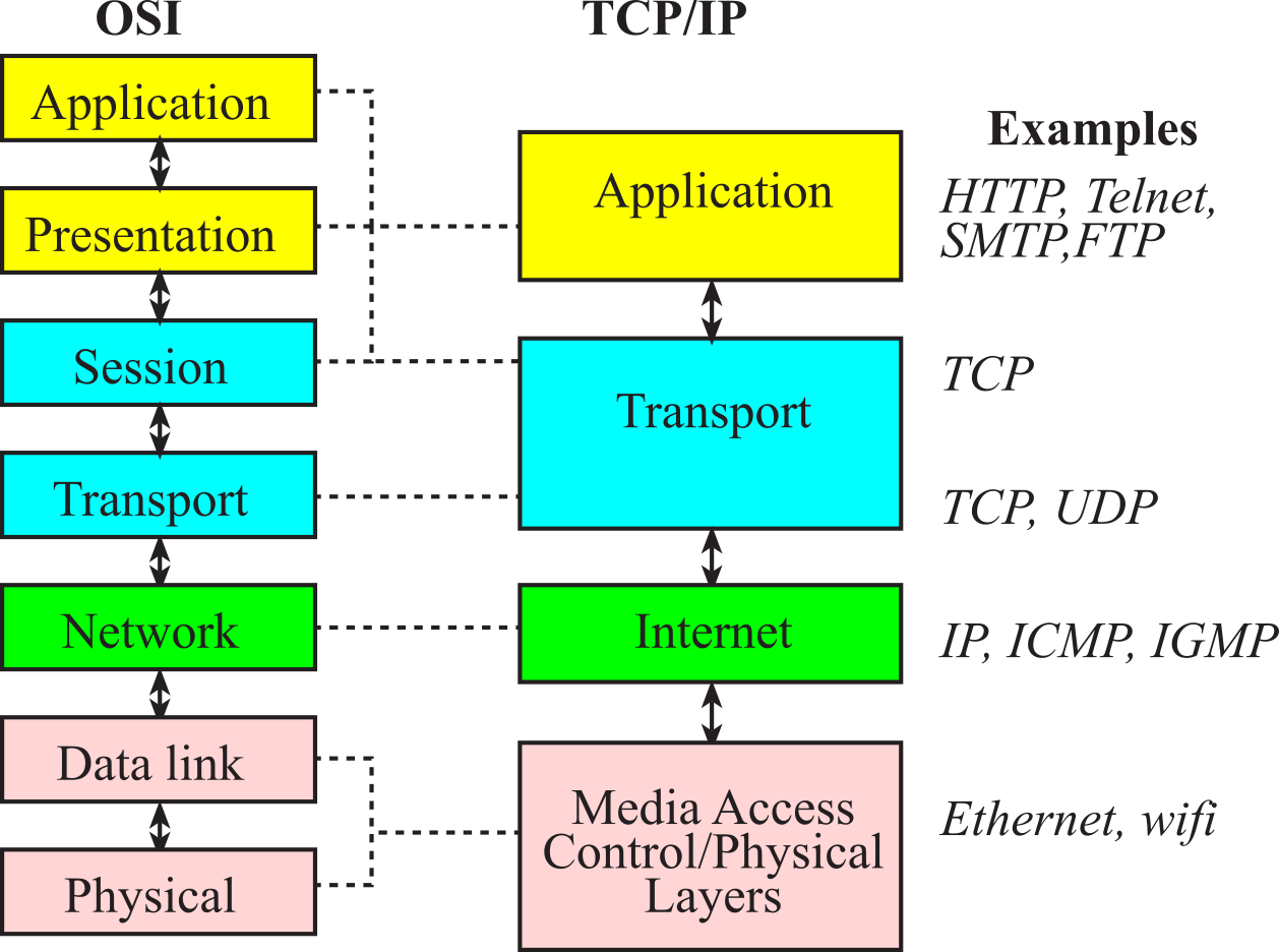
Figure 4.2.1. The TCP/IP model has four layers, which loosely map into the OSI model.
: Think about connecting two microcontrollers together with a UART serial link. What is the physical layer? What is the data link layer?
4.2.2. TCP vs UDP
The TCP/IP model of the Internet does not adhere to such a strict layered structure, but does recognize four broad layers: scope of the software application; the end-to-end transport connection; the internetworking range; and the direct links as shown on the right of Figure 4.2.1. Examples of applications include Telnet, FTP (File Transfer Protocol), and SMTP (Simple Mail Transfer Protocol). Examples of transport include TCP (Transmission Control Protocol) and UDP (User Datagram Protocol). TCP provides reliable, ordered delivery of data from a software task on one computer to another software task running on another computer. For applications that do not require reliable data stream service UDP can be used. UDP provides a datagram service that emphasizes reduced latency over reliability. See Table 4.2.1. Examples of network include IP (Internet Protocol), ICMP (Internet Control Message Protocol) and IGMP (Internet Group Management Protocol). Ethernet is the physical link explored later in this section. In this section we will develop projects at the application layer. The communication of bits happens at the physical layer, frames at the data link layer, packets or datagrams at the network layer, segments at the transport layer, and messages at the application layer.
|
TCP |
UDP |
|
Connection-oriented |
Connectionless |
|
Handshake |
Send and forget |
|
Flow control, retransmit on error |
Best effort |
|
Ordered |
Reordering handled at application layer |
|
HTTP, HTTPs, FTP, SMTP, MQTT, Telnet |
DNS, DHCP, TFTP, SNMP, RIP, VOIP |
|
20-byte header |
8-byte header |
|
Data is read as a byte-stream |
Packets have definite boundaries |
Table 4.2.1. Comparison between TCP and UDP.
: Which is faster UDP or TCP?
4.3. Message Protocols
4.3.1. Domain Name System (DNS)
The Domain Name System (DNS) host can be used to translate domain names to IP addresses, see Figure 4.3.1.
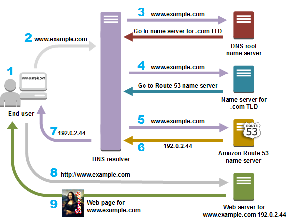
Figure 4.3.1. Domain Name System (DNS), hierarchy. For more information, see https://aws.amazon.com/route53/what-is-dns/.
: How can local caching increase speed of DNS?
4.3.2. Packet formats
The layered format can be seen in the message packet formats, as overviewed in Figure 4.3.2.
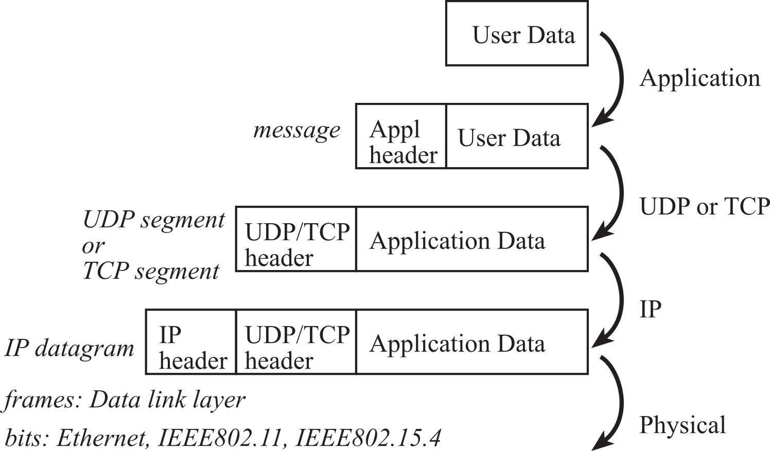
Figure 4.3.2. Overview of message packets used at various layers.
At the lowest level are physical frames. Ethernet frames contain a header, 46 to 1500 bytes of payload, and a trailer. The header includes address, type and length information. If there are less than 46 bytes of Ethernet data, zeros are added (padding) to make the Ethernet payload at least 46 bytes. The trailer includes error checking (CRC). At the IP level, packets include a header and payload. The header of an IP packet includes a 32-bit destination IP address, typically shown as four 8-bit numbers (e.g., 176.31.244.1). Some of these IP addresses are reserved for communicating within nodes on a local network.
Computers that communicate only with each other via TCP/IP, but are not connected to the Internet, need not have globally unique IP addresses. IP addresses for private networks are listed in Table 4.3.1. These IP addresses could be used for embedded systems that use TCP/IP to communicate but are not connected to the internet.
|
Start |
End |
Number of addresses |
|
10.0.0.0 |
10.255.255.255 |
224 |
|
172.16.0.0 |
172.31.255.255 |
220 |
|
192.168.0.0 |
192.168.255.255 |
216 |
Table 4.3.1. Private IP addresses.
Because of the growth of the internet, the 32-bit IP address (IPv4) is being replaced with a 128-bit address (IPv6), which will provide for about 3∙1038 addresses. The IP header is 20 to 40 bytes and contains the source IP address, destination IP address, and length. The UDP header is 8 bytes and contains the source port, destination port, length, and checksum, see Table 4.3.2. The IP address specifies the node, and ports are addresses within the source and destination nodes.
Source port: 16-bit number of the process that sent the packet, could be zero
Destination port: 16-bit number of the process to receive the packet.
Length: 16-bit number specifying the size in bytes of the data to follow
Checksum: 16-bit modulo addition of all data, UDP header, and IP header
Table 4.3.2. UDP header format.
The TCP header is 20 bytes with the possibility of additional and optional information, see Table 4.3.3. The sequence and acknowledgment numbers allow the receiver to properly sort segments of data that were received out of order. The flags specify different modes of TCP communication. The SYN flag means the first of a sequence of packets, and the FIN flag means the last. The RST flag terminates the connection. The URG flag means the urgent pointer specifies a piece of data the application urgently needs. TCP handles variable length packets by dividing the data into smaller segments, each with a defined size based on the "Maximum Segment Size" (MSS) negotiated between the sender and receiver, ensuring reliable transmission by tracking the sequence of these segments and retransmitting any lost packets to maintain the data integrity even if the original data was of a variable length; essentially, it breaks down large data chunks into smaller, manageable pieces for transmission over the network.
Source port: 16-bit number of the process that sent the packet, could be zero
Destination port: 16-bit number of the process to receive the packet.
Sequence number: 32-bit number defining the position of this data
Acknowledgement: 32-bit number of the next data expected to be received
Hlen: 4-bit field of the header size (including options) divided by 4
Flags: 6-bit field with FIN, SYN, RST, PSH, ACK, and URG
Window: 16-bit number specifying the number of bytes the receiver can accept
Checksum: 16-bit modulo addition of all data, TCP header, and IP header
Urgent pointer: 16-bit field pointing to a place in the stream urgently needed
Table 4.3.3. TCP header format.
Request for Comments (RFC) is a series of publications standardizing the use of the internet. Table 4.3.4 shows some typical uses of port numbers.
|
Port Number |
Transport Protocol |
Service Name |
RFC |
|
20,21 |
TCP |
File Transfer Protocol (FTP) |
959 |
|
22 |
TCP and UDP |
Secure Shell (SSH) |
4250-4256 |
|
23 |
TCP |
Telnet |
854 |
|
25 |
TCP |
Simple Mail Trans Protocol (SMTP) |
5321 |
|
53 |
TCP and UDP |
Domain Name Server (DNS) |
1034-1035 |
|
67, 68 |
UDP |
Dynamic Host Config Protocol (DHCP) |
2131 |
|
80 |
TCP |
HyperText Transfer Protocol (HTTP) |
2616 |
|
110 |
TCP |
Post Office Protocol (POP3) |
1939 |
|
123 |
UDP |
Network Time Protocol (NTP) |
5905 |
|
179 |
TCP |
Border Gateway Protocol (BGP) |
4271 |
|
443 |
TCP and UDP |
HTTP Secure (HTTPS) |
2818 |
|
500 |
UDP |
Internet Sec Assoc Key Man (ISAKMP) |
2408-2409 |
Table 4.3.4. Standard usage of port numbers.
: How does UDP handle variable length messages?
: How does TCP handle variable length messages?
4.4. Client-Server Paradigm
The client-server paradigm is the dominant communication pattern over the Internet. The socket API supports two forms of this paradigm, a TCP-based connection-oriented form and a UDP-based connection-less form. Table 4.4.1 shows various popular applications and the underlying application and transport protocols they use.
|
Application |
Application Protocol |
Transport Protocol |
|
|
SMTP |
TCP |
|
Remote terminal |
Telnet |
TCP |
|
Web |
HTTP |
TCP |
|
File transfer |
FTP |
TCP |
|
Streaming media |
HTTP, RTP |
TCP or UDP |
|
Telephony |
SIP, RTP, Skype |
TCP or UDP |
Table 4.4.1. Applications their protocols and Transport protocol on which they depend.
The popular Hyper-Text Transfer Protocol (HTTP), which is used in the implementation of the World Wide Web (WWW) is TCP-based. A web browser like Firefox is a client (a HTTP client) and a web server like openweathermap.org is a server (a HTTP server). The paradigm can be seen to function as outlined in Figure 4.4.1.
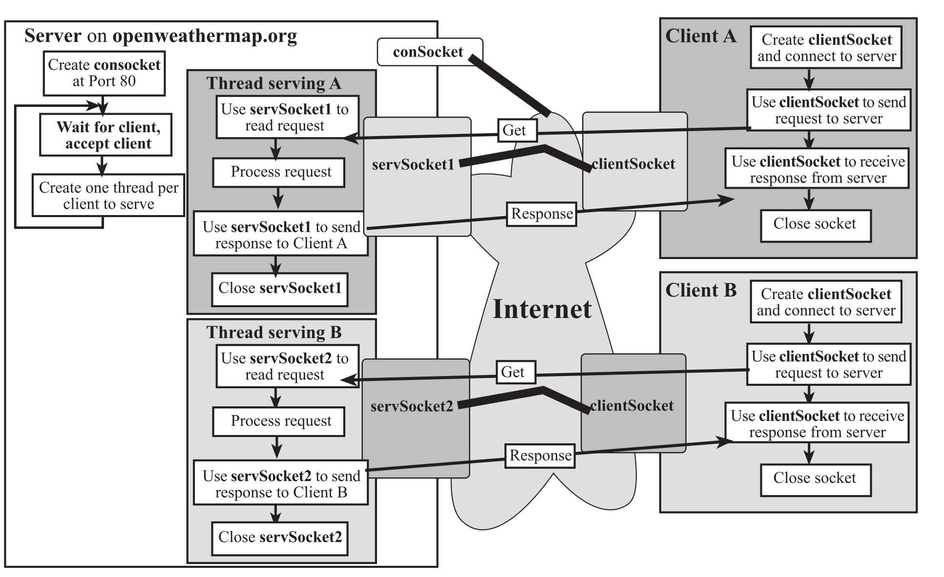
Figure 4.4.1. Client-Server paradigm with a multi-threaded server, serving multiple clients.
A server running at a machine (in the next section we will communicate with openweathermap.org) creates a socket bound to a port. This port number is either a standard port or one chosen specifically for the service. For example, if the server is a web server that is publicly accessible, then the port number is 80. On the other hand, if it's a proprietary server, the service may choose an arbitrary number for xyz (say 6565) and let clients know about it so they can connect for service. This socket is called a connection socket (conSocket) where the server waits for connection requests from clients. A client that wants to access the service provided by the server creates a client socket (clientSocket). The client needs to know the hostname and the port at which the service is running to establish the connection using the client socket. Once the server sees the request, it accepts it on a separate socket (shown as servSocket1 or servSocket2 in the Figure 4.4.1). It does not serve the client on the connection socket because, if it takes too long to serve the client then the server will be inaccessible to other clients seeking service. By accepting each client with a separate socket, the server can remain ready for connection requests from new clients.
Once the server accepts a client (say A) it creates a thread to service that client by passing to the thread the socket at which the client was accepted (server tells Client A about servSocket1). The main thread is now free to accept other clients. The exchange between client A and the thread serving it may involve multiple messages transferred back and forth or a single request/response (shown as Get and Response in the figure). A Web Browser like Firefox makes one connection for each object it requests from a Web Server. Note that each client connection is to port 80, which is a standard port at which Web Servers run.
: What device initiates communication?
4.5. Web server
This first application creates a web server that maintains a web page displaying local data, see Figures 4.5.1 and 4.5.2. The components of the system are a sensor and sensor interface, an EK-TM4C1294XL LaunchPad, Texas Instruments TivaWare, and a router connected to the Internet. The Dynamic Host Configuration Protocol server provides an IP address, and is typically initiated via a DHCP broadcast, when it connects. DHCP provided the address 192.168.0.107, a local address on its network. This example was built on top of the uIP stack delivered as part of TivaWare. First, you need to download TivaWare. Find the enet_uip example found in the following folder:
TivaWare_C_Series-2.1.0.12573\examples\boards\ek-tm4c1294xl\enet_uip
I copied this example and changed the web server as shown in Program 4.5.1.
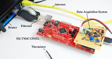
Figure 4.5.1. The thermistor measures temperature and the LaunchPad serves pages on the internet.
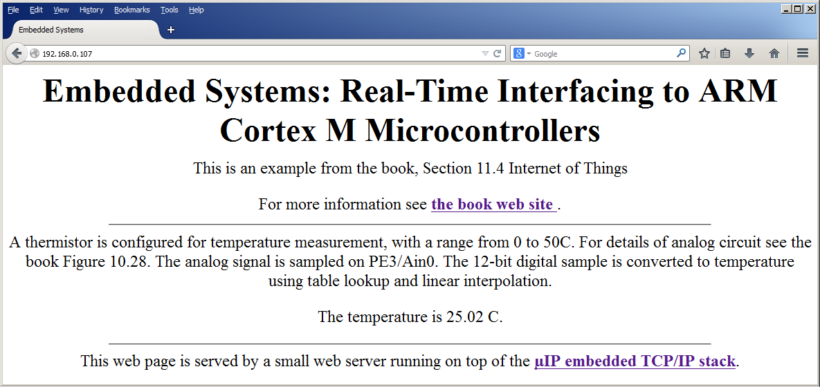
Figure 4.5.2. The thermistor measures temperature and the LaunchPad serves pages on the internet.
Program 4.5.1 shows the code you need to modify to create your own remote sensor smart object. When another node sends a request to this server, this node will respond with html code to render the page. The page is divided into three parts. The first part (default_page_buf1of3) and last part (default_page_buf3of3) are fixed. The application callback function, httpd_appcall, is invoked when the web page is requested. This callback function calls our application function Board_Update which collects sensor data from the thermistor and rebuilds the middle part of the html code (default_page_buf2of3). The meta code automatically refreshes every 5 seconds.
const
char default_page_buf1of3[] =
"HTTP/1.0 200 OK\r\n"
"Server: UIP/1.0 (http://www.sics.se/~adam/uip/)\r\n"
"Content-type: text/html\r\n\r\n"
"<!DOCTYPE HTML PUBLIC \"-//W3C//DTD HTML 4.01
Transitional//EN"
"http://www.w3.org/TR/html4/loose.dtd\">"
"<html> <head>"
"<meta http-equiv=\"refresh\"
content=\"5\">"
"<title>Embedded Systems</title></head>"
"<body> <center>"
"<h1>Embedded Systems: Real-Time Interfacing"
"to ARM Cortex M Microcontrollers</h1>"
"<p>This is an example from Section 4.4 Internet of
Things</p>"
"<p> For more information see "
"<a
href=\"http://users.ece.utexas.edu/~valvano/arm/outline.htm\">"
"<b>the book web site</b> </a>."
"<hr width=\"75%\">"
"<p>A thermistor is configured for temperature measurement, "
"with a range from 0 to 50C. "
"For details of analog circuit see the Chapter 10. "
"The analog signal is sampled on PE3/Ain0. "
"The 12-bit digital sample is converted to temperature using "
" table lookup and linear interpolation.</p> "
"<p>The temperature is ";
uint32_t
const buf1of3_Size = (sizeof(default_page_buf1of3) - 1);
char
default_page_buf2of3[] = "12.01";
uint32_t
buf2of3_Size = (sizeof(default_page_buf2of3) - 1);
const
char default_page_buf3of3[] =
" C.</p>"
"<hr width=\"75%\">"
"<p>This web page is served by a small web server running on top of
"
"the <a
href=\"http://www.sics.se/~adam/uip/\"><b>µIP
embedded TCP/IP "
"stack</b></a>.</center> </body> </html>";
uint32_t
const buf3of3_Size = (sizeof(default_page_buf3of3) - 1);
void
Board_Update(void){uint32_t data,temperature;
data = ADC0_InSeq3(); // 12-bit ADC, 0 to 4095
temperature = ADC2Temperature(data); // temperature, 0.01C
Fix2Str(temperature,default_page_buf2of3); // 5 ASCII characters
buf2of3_Size = 5; // in this case it is fixed size (but it could vary)
}
Program 4.5.1. The thermistor measures temperature and the LaunchPad serves pages on the internet.
4.6. UDP communication over wifi
The approach for implementing a smart object over wifi is to begin with a hardware/software platform that implements IEEE801.11 wifi. The CC3100BOOST is a BoosterPack that can be used with most TI LaunchPads, see Figure 4.6.1. The emulation module can be used early in a project to develop wireless applications using a "generic" microcontroller. After a prototype is configured, the project can select a microcontroller and design the actual smart object. In this design we will use either of the two TM4C LaunchPads and develop a solution that transmits UDP packets from one smart object to another. UDP is simpler than TCP and appropriate for applications requiring simplicity and speed. Furthermore, to use UDP the application must tolerate lost or out of order packets. UDP provides a best-effort datagram delivery service.
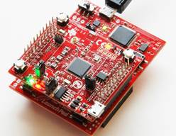
Figure 4.6.1. The CC3100 BoosterPack provides IEEE802.11 wireless connectivity.
The actual TCP/IP software stack resides in firmware on the booster pack itself. Therefore, when using any of the wireless booster packs the first step is to upgrade the firmware. One way to upgrade the firmware is to use the CC31XXEMUBOOST emulation module. The examples of this section ran on version 3.3 booster packs without needing to upgrade the firmware.
Program 4.6.1 shows the client software, which samples the ADC and sends UDP packets. Line 1 specifies the name of the access point (AP) to which the node will connect. There is a mechanism using SmartConfig to automate this discovery, but in this example, I named the AP Valvano so I used a manual method to define the connection between the node and AP. The UDP payload will have a type field, which is defined in line 2. The destination IP address is hard-coded in line 3. For this application, the server was at IP address at 192.168.0.101, which in hex is C0.A8.00.65. The port number, which is a 16-bit value defining which process in the server should receive the data, is specified in line 4. There are a long list of registered port numbers that have special purposes, so I chose a port number larger than 1024 to avoid selecting any of these special purpose port numbers. Lines 5 and 6 define the payload for the UDP packet. Line 15 sets the bus clock to 50 MHz. The PLL needs to be active for the ADC to operate. Line 16 initializes ADC channel 7 using PD0. Line 17 initializes the CC3100. After executing line 18 we will be connected and have IP address. Line 19 will return the network configuration. Lines 21-24 define the address and port to which the USP packet will be sent. Line 25 defines and opens a socket. In this example we leave the socket open, but it is ok to close the socket, go into low-power mode, and reopen the connection after sleeping. Lines 26-29 will sample the ADC and create a new message. Line 30 sends the UDP packet through the open socket. The wait in line 32 defines the rate at which packets are sent. Each of the wifi functions will return a success flag (error code). In this simple program we ignored the return values, assuming it was ok. In the version on the web, the process is restarted on error.
#define SSID_NAME "Valvano" // AP to connect to 1
#define ATYPE 'a' // analog data type 2
#define IP_ADDR 0xC0A80065 // server IP 3
#define PORT_NUM 5001 // Port number to be used 4
#define BUF_SIZE 12 // 5
UINT8 uBuf[BUF_SIZE]; // UDP packet payload 6
int main(void){
UINT8 IsDHCP = 0;
_NetCfgIpV4Args_t ipV4;
SlSockAddrIn_t Addr;
UINT16 AddrSize = 0;
INT16 SockID = 0;
UINT32 data;
unsigned char len = sizeof(_NetCfgIpV4Args_t);
initClk(); // PLL 50 MHz, ADC needs PPL active 15
ADC0_InitSWTriggerSeq3(7); // Ain7 is on PD0 16
sl_Start(0, 0, 0); // Initializing the CC3100 device 17
WlanConnect(); // connect to AP 18
sl_NetCfgGet(SL_IPV4_STA_P2P_CL_GET_INFO,&IsDHCP,&len, // 19
(unsigned char *)&ipV4); // 20
Addr.sin_family = SL_AF_INET; // 21
Addr.sin_port = sl_Htons((UINT16)PORT_NUM); // 22
Addr.sin_addr.s_addr = sl_Htonl((UINT32)IP_ADDR); // 23
AddrSize = sizeof(SlSockAddrIn_t); // 24
SockID = sl_Socket(SL_AF_INET,SL_SOCK_DGRAM, 0); // 25
while(1){
uBuf[0] = ATYPE; // analog data type 26
uBuf[1] = '='; // 27
data = ADC0_InSeq3(); // 0 to 4095, Ain7 is on PD0 28
Int2Str(data,(char*)&uBuf[2]); // 6 digit number 29
sl_SendTo(SockID, uBuf, BUF_SIZE, 0, // 30
(SlSockAddr_t *)&Addr, AddrSize); // 31
ROM_SysCtlDelay(ROM_SysCtlClockGet() / 25); // 40ms 32
}
}
Program 4.6.1. Client software that measures ADC data and sends UDP packets.
: Why is the IP address included in the sl_SendTo call?
: What does DGRAM mean?
Program 4.6.2 shows the server software, which accepts UDP packets and plots the data on an ST7735 graphics LCD. Line 1 specifies the name of the access point (AP) to which the node will connect. The client and server use the same AP, which I named Valvano, so I used the manual method to define the connection between the node and AP. The UDP payload will have a type field, which is defined in line 2. Lines 16, 22-25 configure the wifi connection in a similar way as the client. Lines 17-20 initialize the ST7735 LCD and output a welcome message. Line 21 configures the LCD graphics routines specifying the range on the y-axis of the plot. Raw ADC data will be plotted versus time. Lines 26-29 define an IP address and port to use. Line 31 defines and opens a socket, and lines 32-33 bind the port to that socket. Lines 34-35 receive a UDP packet. Just like the client, we leave the socket open. If we wished to save power, we could close the socket, go into low-power mode, and reopen the connection after sleeping. Lines 36-51 decode the packet and plot the data on the LCD.
#define SSID_NAME "Valvano" // AP to connect to 1
#define ATYPE 'a' // analog data type 2
#define IP_ADDR 0xC0A80065 // server IP 3
#define PORT_NUM 5001 // Port number to be used 4
#define BUF_SIZE 12 // 5
UINT8 uBuf[BUF_SIZE]; // UDP packet payload 6
int main(void){
UINT8 IsDHCP = 0;
_NetCfgIpV4Args_t ipV4;
SlSockAddrIn_t Addr, LocalAddr;
UINT16 AddrSize = 0;
INT16 SockID = 0;
INT16 Status = 1; // ok
UINT32 data;
unsigned char len = sizeof(_NetCfgIpV4Args_t);
initClk(); // PLL 50 MHz, ADC needs PPL active 16
ST7735_InitR(INITR_REDTAB); // Initialize 17
ST7735_OutString("Internet of Things\n"); // 18
ST7735_OutString("Embedded Systems\n"); // 19
ST7735_OutString("Vol. 2, Valvano"); // 20
ST7735_PlotClear(0,4095); // range from 0 to 4095 21
sl_Start(0, 0, 0); // Initializing the CC3100 device 22
WlanConnect(); // connect to AP 23
sl_NetCfgGet(SL_IPV4_STA_P2P_CL_GET_INFO,&IsDHCP,&len, // 24
(unsigned char *)&ipV4); // 25
LocalAddr.sin_family = SL_AF_INET; // 26
LocalAddr.sin_port = sl_Htons((UINT16)PORT_NUM); // 27
LocalAddr.sin_addr.s_addr = 0; // 28
AddrSize = sizeof(SlSockAddrIn_t); // 29
while(1){
SockID = sl_Socket(SL_AF_INET,SL_SOCK_DGRAM, 0); // 31
Status = sl_Bind(SockID, (SlSockAddr_t *)&LocalAddr, // 32
AddrSize); // 33
Status = sl_RecvFrom(SockID, uBuf, BUF_SIZE, 0, // 34
(SlSockAddr_t *)&Addr, (SlSocklen_t*)&AddrSize );// 35
if((uBuf[0]==ATYPE)&&(uBuf[1]== '=')){ // 36
int i,bOk; uint32_t place; // 37
data = 0; bOk = 1; // 38
i=4; // ignore possible negative sign 39
for(place = 1000; place; place = place/10){ // 40
if((uBuf[i]&0xF0)==0x30){ // ignore spaces 41
data += place*(uBuf[i]-0x30); // 42
}else{ // 43
if((uBuf[i]&0xF0)!= ' '){ // 44
bOk = 0; // 45
} // 46
} // 47
i++; // 48
} // 49
if(bOk){ // 50
ST7735_PlotLine(data); // 51
ST7735_PlotNextErase(); // 52
}
}
}
}
Program 4.6.2. Server software that receives UDP packets and plots results on the LCD.
: What is the difference between LocalAddr and Addr in Program 4.6.2?
Since UDP transmission is "best effort" we could lose packets or receive packets out of order. In this simple example we will not know if either of these errors were to occur. If we wished to have a more reliable transmission, we could have used TCP. Program 4.6.1 line 25 would have specified a socket stream instead of a datagram. To create a TCP communication, use the example software in the tcp_socket folder.
SockID = sl_Socket(SL_AF_INET,SL_SOCK_STREAM, 0); // TCP socket
4.7. Access a Weather Server using TCP
In this section, we will have the Launchpad connected to a web server running at openweathermap.org, a public server that gives weather information for any city in the world. So, the process is to create a socket and connect to the weather server running on openweathermap.org at port 80. Once connected, we send it a request using the HTTP GET command. The server responds with a well-formatted string containing weather details for the city whose weather information was sought in the GET request.
The CC3100GetWeather_4C123 application creates a web client that fetches weather data from a server. To see the features of the server, go to openweathermap.org, enter Austin Texas into the search box, and click search. The goal of this smart object is to display weather data on the LCD. The approach for implementing a smart object over wifi is to begin with a hardware/software platform that implements IEEE801.11 wifi. The CC3100BOOST is a BoosterPack that can be used with the TM4C123 LaunchPad as shown in Figure 4.7.1.
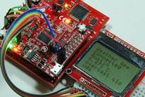
Figure 4.7.1. Client-Server paradigm with the LaunchPad+CC3100 as a client fetching weather data.
A version of this client is shown in Program 4.7.1. To run this application, you will need an access point (AP). The first step will be to edit lines 97-99 to define connection to your access point, change these three lines in main.c in CC3100GetWeather_4C123
#define SSID_NAME "Valvano" // Access point name
#define SEC_TYPE SL_SEC_TYPE_WPA
#define PASSKEY "Calvin" // Password
Notice the server web address and the HTTP GET request in lines 97 and 98. You can see/edit the GET request sent to the weather server. You could edit line 206 to see weather in a different city if you wish. The ASCII code %20 represents the space character in the name, rather than a delimiter in the GET request.
#define REQUEST "GET /data/2.5/weather?q=Austin%20Texas&
units=metric HTTP/1.1\r\n
User-Agent: Keil\r\nHost:api.openweathermap.org\r\n
Accept: */*\r\n\r\n"
Notice the server web address and the HTTP GET request in lines 97 and 98. You can see/edit the GET request sent to the weather server. You could edit line 206 to see weather in a different city if you wish. Lines 209-212 initialize the LaunchPad allowing for output on the UART, switch input, and LED output. The function call on line 213 configures the policies on the SimpleLink software driver. Line 215 will start the CC3100 hardware. Lines 217-223 will connect to the access point. Programs 4.6.1 and 4.7.1 called the function sl_NetCfgGet() at this point to determine the IP address the AP assigned to this client. The local IP address will not be needed in this example. Lines 226-228 use the DNS to translate the logical IP address (openweathermap.org) to its physical address (144.76.83.20). Lines 230-236 open a socket in the weather server. As we saw in Figure 4.4.1, we send the socket request to port 80 of the public conSocket and the server response by giving us our own private servSocket socket. The SimpleLink driver keeps a data structure of the details of this connection and we can refer to it as a simple number (e.g., SockID). Lines 239-240 send the TCP packet containing the GET request to the server. Line 241 receives the response from the server. Embedded in the response are the weather details we requested. Line 242 closes the socket, and line 245 prints the response out UART0. There are three ways to observe the weather data: 1) over the UART using a terminal program like PuTTY, 2) looking at Recvbuff in the debugger, or 3) displaying on the LCD. To understand how the client-server paradigm works, place breakpoints at these lines in main.c:
Line 220 Connect to access point (name, password, type)
Line 227 Domain Name System (web address to IP address)
Line 236 Create Socket, open connection (IP address, port 80)
Line 240 Send TCP (weather request)
Line 241 Receive TCP
int main(void){int32_t retVal; SlSecParams_t secParams; //207
char *pConfig = NULL; INT32 ASize = 0; SlSockAddrIn_t Addr;
initClk(); // PLL 50 MHz 209
UART_Init(); // Send data to PC, 115200 bps 210
LED_Init(); // initialize LaunchPad I/O 211
UARTprintf("Weather App\n"); //212
retVal = configureSimpleLinkToDefaultState(pConfig); //213
if(retVal < 0)Crash(4000000);
retVal = sl_Start(0, pConfig, 0); //215
if((retVal < 0) || (ROLE_STA != retVal) ) Crash(8000000);
secParams.Key = PASSKEY; //217
secParams.KeyLen = strlen(PASSKEY); //218
secParams.Type = SEC_TYPE; // OPEN, WPA, or WEP 219
sl_WlanConnect(SSID_NAME, strlen(SSID_NAME),0,&secParams,0);//220
while((0==(g_Status&CONNECTED))||(0== (g_Status&IP_AQUIRED))){
_SlNonOsMainLoopTask();} //222
UARTprintf("Connected\n");
while(1){
strcpy(HostName,"openweathermap.org"); //226
retVal = sl_NetAppDnsGetHostByName(HostName, //227
strlen(HostName),&DestinationIP, SL_AF_INET); //228
if(retVal == 0){ //229
Addr.sin_family = SL_AF_INET; //230
Addr.sin_port = sl_Htons(80); //231
Addr.sin_addr.s_addr = sl_Htonl(DestinationIP); //232
ASize = sizeof(SlSockAddrIn_t); //233
SockID = sl_Socket(SL_AF_INET,SL_SOCK_STREAM, 0); //234
if(SockID >= 0){
retVal=sl_Connect(SockID,(SlSockAddr_t *)&Addr,ASize);}//236
if((SockID >= 0)&&(retVal >= 0)){
strcpy(SendBuff, REQUEST); //239
sl_Send(SockID, SendBuff, strlen(SendBuff), 0); //240
sl_Recv(SockID, Recvbuff, MAX_RECV_BUFF_SIZE, 0); //241
sl_Close(SockID); //242
LED_GreenOn(); UARTprintf("\r\n\r\n");
UARTprintf(Recvbuff); UARTprintf("\r\n");}} //245
while(Board_Input()==0){}; // wait for touch
LED_GreenOff();
}
}
Program 4.7.1. Client software that fetches weather data from openweathermap.org.
: What does STREAM mean?
: Why is the IP address not included in the sl_Send call?
4.8. If-this-then-that
There are many options to create services in the cloud with which your IoT device could interact. One easy-to-use cloud service is called If This Then That. IFTTT is a website that lets us set up rules and triggers to automate a process. You can use the CC3100 booster or an ESP8266 wifi device. Like the openweathermap.org example, the hardware must connect to a wifi hotspot. Use the DNS to find the IP address of https://maker.ifttt.com, open a socket to this IP address, and POST TCP messages to this website.
In this first example, we will configure the device so that if we push a button on the LaunchPad, it will send us an email. Sign up for an IFTTT account at ifttt.com and associate it with an email address for testing your LaunchPad. Create a new applet from the interface. An applet is a logical connection between two web services supported in IFTTT. Choose webhooks as the service (this) that will trigger the applet. Click "Receive a web request" and call the event name "button_pressed". Click "Create trigger". Next, specify the action to perform on a trigger (that). Choose the action service by typing "email" and select email. You will have to connect your email to IFTTT by receiving a PIN via email and typing it back into IFTTT. Choose an action "send me an email". Set your subject to "LaunchPad Email" and leave the body with the default values. Value1 Value2 and Value3 will be data fields you could use to send information about the device in the email body. Click "Create action" and then your applet is complete. Now we need to go into the settings of the Webhooks service. Go into the settings from my applets menu. Here you will see the URL you need to navigate to with your unique IFTTT key after https://maker.ifttt.com/user/{key}. Save a copy of this key. If you go to this URL, it will trigger a Webhooks evebt and send you an email.
https://maker.ifttt.com/trigger/button_pressed/with/key/{key}
where {key} is your key. For the device to send an email through IFTTT the device will need to send a POST TCP packet to IFTTT. You will replace the <X> with your IFTTT key. Run this code to verify it will send an email from your device. The code for the #define REQUEST is all on one line.
#define WEBPAGE
"maker.ifttt.com"
#define REQUEST "POST
/trigger/button_pressed/with/key/<X> HTTP/1.1\n
Host: maker.ifttt.com\n
User-Agent: CCS/9.0.1\nConnection:
close\n
Content-Type: application/json\n
Content-Length: 68\n\n
{\"value1\" : \"IoT
example\", \"value2\" : \"Hello\",
\"value3\" : \"World!\" }\n\n"
In this second example, we will configure the device so that data is logged from the LaunchPad onto a google spreadsheet. Create another applet on your IFTTT account. Like the email example, this applet will be triggered by a Webhooks event. Give it a different name from button_pressed, such as log_data. However, the action event will be to add a row to a spreadsheet on your GoogleDrive. You will pass device data in the three fields Value1 Value2 and Value3. The free version of IFTTT limits the rate at which your device can trigger. If you trigger too fast, it will shut down temporarily. The POST message is like an email.
#define REQUEST "POST /trigger/log_data/with/key/<X> HTTP/1.1\n Host: maker.ifttt.com\n User-Agent: CCS/9.0.1\n Connection: close\nContent-Type: application/json\n Content-Length: 165\n\n {\"value1\" : \"0, -23, -96, -393, -470, -435, -363, -7, 74\", \"value2\" : "0, 391, 471, 432, 360, 3, -78, -50, 20\", \"value3\" : "90, 98, -179, -169, -89, -83, 0, 6, 89\" }\n\n"
Figure 4.8.1 shows the GoogleSheets where the above post is shown in the last row
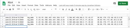
Figure 4.8.1. GoogleSheet with data logged from the LaunchPad using IFTTT.
4.9. Blynk
IFTTT was a simple approach to send data from the IoT device to the cloud. Blynk, on the other hand, supports interactive two-way communication between your cell phone and a smart object over the internet. Like other internet examples, the hardware must connect to a wifi hotspot, use the DNS to find the IP addresses, open sockets, and GET/POST TCP messages. However, Blynk code must be programmed onto your ESP8266 or CC3100. Search https://blynk.io/ for the firmware code for your wifi device. You must reprogram the wifi device with the Blynk firmware. Figure 4.9.1 shows the hardware interface. The ESP8266 requires up to 215 mA supply current, so it should have its own +3.3V regulator.
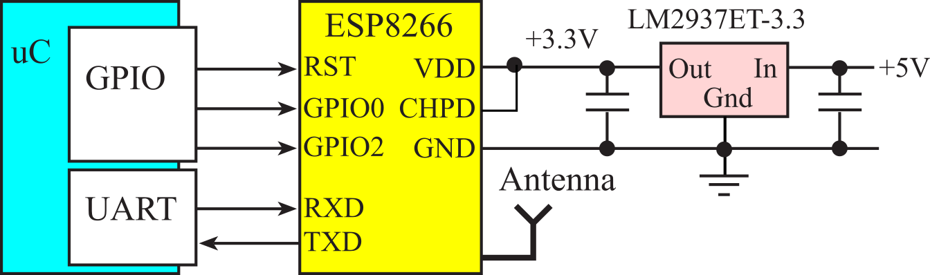
Figure 4.9.1. A smart object with an ESP8266 interface uses three GPIO outputs and one full-duplex UART.
The fundamental communication approach involves virtual pins. Virtual pins V0-V15 are used to send information from the phone to the smart object. Virtual pins V70-V99 are used to send information from the smart object to the phone. The smart object interfaces with a wifi-enabled device like the ESP8266 or the CC3100 using UART. Both the phone and the smart object act as clients to the Blynk server. When the user clicks on the phone, data is sent to smart object (bold dashes in Figure 4.9.2):
A TCP packet is sent via virtual pin V0-V15 from phone to the Blynk server,
That request is relayed to the ESP8266 using a second TCP packet,
The information is then sent across the UART, and
The data is interpreted by the microcontroller in the smart object.
When the smart object wishes to send data to the phone, (dotted line in Figure 4.9.2):
The smart object sends a simple message to the ESP8266 via UART,
The ESP8266 sends a TCP packet to the Blynk server via virtual pin V70-V99,
That request is relayed to the phone using a second TCP packet, and
The Blynk app on the phone displays the information as configured.
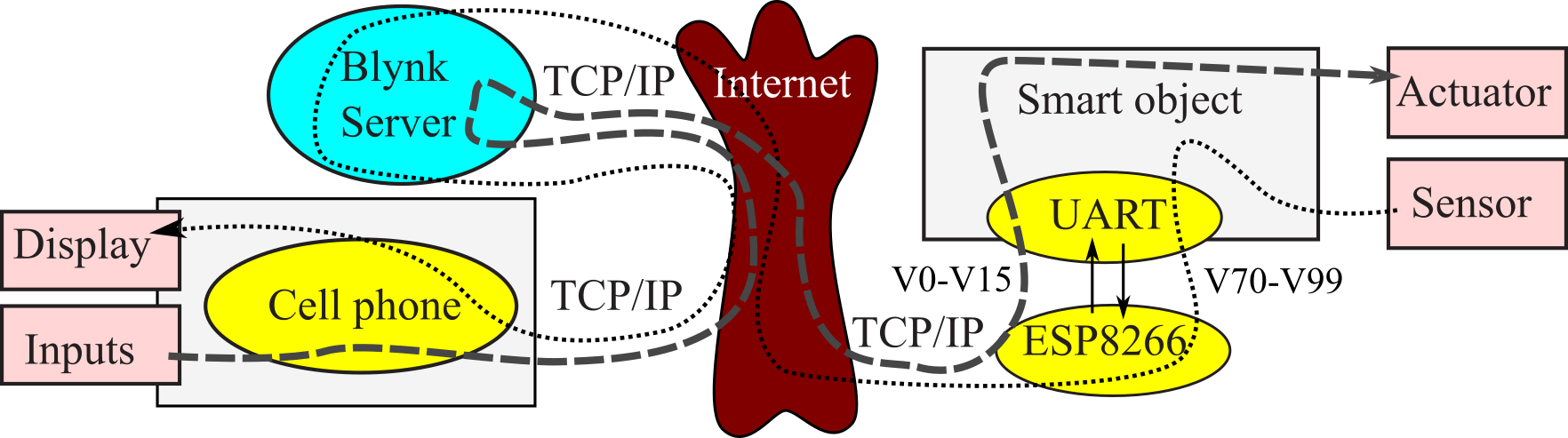
Figure 4.9.2. Data flow graph of IoT device using Blynk.
The first step is to create an account and download the Blynk app to your cell phone (iPhone or Android). Figure 4.9.3 shows on the app that one might use to control an alarm clock. There are five momentary input buttons (V1-V5), three step switches (V7-V9), and three numerical displays (V74-V76).
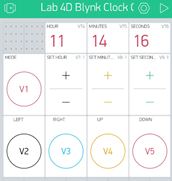
Figure 4.9.3. A Blynk app one might use to control an alarm clock.
Figure 4.9.4 shows five sliders used to pass data from the phone to the smart object, and five numerical displays showing data from the smart object.
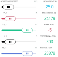
Figure 4.9.4. A Blynk app one might use to interact with a motor controller.
Program 4.9.1 is an example high-level code that connects a smart device with the phone via Blynk. In this example, there is one virtual pin (VP1) connecting a button on the app with an LED on the smart object. There is a second virtual (VP74) connecting a switch on the smart object with an associated display on the phone. Timer2 periodically checks for incoming messages from the Blynk server. If a VP1 message is received, the LED is updated. Timer3 periodically checks the status of a switch. If the switch has changed, a VP74 message is sent to the server. The communication protocol between the smart object and the Blynk firmware on the ESP8266 is comma separated ASCII text:
Pin number, Integer Value, Floating Value, <CR>
uint32_t LastSwitch; // VP74
char serial_buf[64];
char Pin_Number[2] = "99"; // invalid pin number
char Pin_Integer[8] = "0000";
char Pin_Float[8] = "0.0000";
uint32_t pin_num;
uint32_t pin_int;
void SmartObject_to_Blynk(uint32_t pin,uint32_t value){
if((pin < 70)||(pin > 99)){
return; // ignore illegal requests
}
ESP8266_OutUDec(pin); // Send the Virtual Pin #
ESP8266_OutChar(',');
ESP8266_OutUDec(value); // Send the current value
ESP8266_OutChar(',');
ESP8266_OutString("0.0\n"); // not used
}
void Blynk_to_SmartObject(void){int j; char data;
// Check to see if a there is data in the RXD buffer
if(ESP8266_GetMessage(serial_buf)){ // false if none
// serial_buf has data from the ESP8266
// Rip the 3 fields out of the CSV data, sequence is:
// Pin #, Integer Value, Float Value.
strcpy(Pin_Number, strtok(serial_buf, ","));
strcpy(Pin_Integer, strtok(NULL, ","));
strcpy(Pin_Float, strtok(NULL,
pin_num = atoi(Pin_Number); // ASCII to integer
pin_int = atoi(Pin_Integer);
if(pin_num == 0x01) { // VP1 sent to LED
Port_Output(pin_int); // LED
}
}
}
void SendInformation(void){
uint32_t thisSwitch = Port_Input(); // read switch
if(thisSwitch != LastSwitch){ // send only if changed
SmartObject_to_Blynk(74, thisSwitch); // VP74
}
LastSwitch = thisSwitch;
}
int main(void){
Clock_Init(); // set Bus clock to fastest speed
DisableInterrupts(); // Disable during inits
Port_Init();
LastSwitch = Port_Input();
ESP8266_Init(); // Enable ESP8266 Serial Port
ESP8266_Reset(); // Reset the WiFi module
ESP8266_SetupWiFi(); // Setup Blynk Server
Timer2_Init(&Blynk_to_SmartObject,TIME10ms);
Timer3_Init(&SendInformation, TIME500ms);
EnableInterrupts();
while(1) {
WaitForInterrupt(); // low power mode
}
}
Program 4.9.1. A simple two-way communication channel between smart object and phone using Blynk.
4.10. MQTT
MQTT is a publish-subscribe messaging protocol, classified as a pub-sub. The MQTT name was inherited from a project at IBM. The name Message Queue Telemetry Transport has been dropped from use and simply identified by MQTT. Like CoAP, it was built with resource-constrained devices in mind. MQTT has a lightweight packet structure designed to conserve both memory usage and power. A connected device subscribes to a topic hosted on an MQTT broker. Every time another device or service publishes data to a topic, all the devices subscribed to it will automatically get the updated information.
MQTT uses an intermediary, which is called a broker. There are clients, or publishers, which produce data. The MQTT protocol calls this data a topic, and each topic must have a unique identifier. Consider an example where one device measures temperature (producer) and two other devices are interested in temperature (consumers). In Figure 4.10.1 shows a temperature sensor, which is an embedded device with a sensor attached, and it periodically publishes the topic "temperature". Publishing a topic means sending data to the broker. The broker keeps track of all the published information. Subscribers are the consumers who are interested in the data. What the subscribers do is express their interest in a topic by sending a subscription message. The solid arrows in Figure 4.10.1 are the data flow with two devices that have subscribed to the topic "temperature". Whenever new data is available, the broker will serve it to both subscribers.
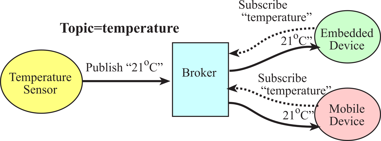
Figure 4.10.1. With MQTT, the broker acts as an intermediary between producers and consumers.
The fundamental advantage of a pub/sub model for communication in contrast with a client-server model is the decoupling of the communicating entities in space, time and synchronization. That is, the publisher and subscribed do not need to know each other, they do not run at the same time, and they can act asynchronously. Other advantages of MQTT are the use of a publish-subscribe message queue and the many-to-many broadcast capabilities. Using a TCP connection to the MQTT broker, sending messages of limited bandwidth back and forth is simple and straightforward.
There are three operations a client can perform with the broker, see Figure 4.10.2. The operation includes the Client ID, which must be unique. Each operation is acknowledged by the broker. The connect operation is like dialing the telephone. The client initiates the connection, and once connected each can communicate until one party hangs up. The subscribe operation tells the broker the client is interested in a specific topic. The unique identifiers are defined by the broker. The broker will send the client new information when available. The subscribe operation provides the broker with the new information. The client can also send a keepalive message, every 60 seconds, to prevent the broker from hanging up due to inactivity.
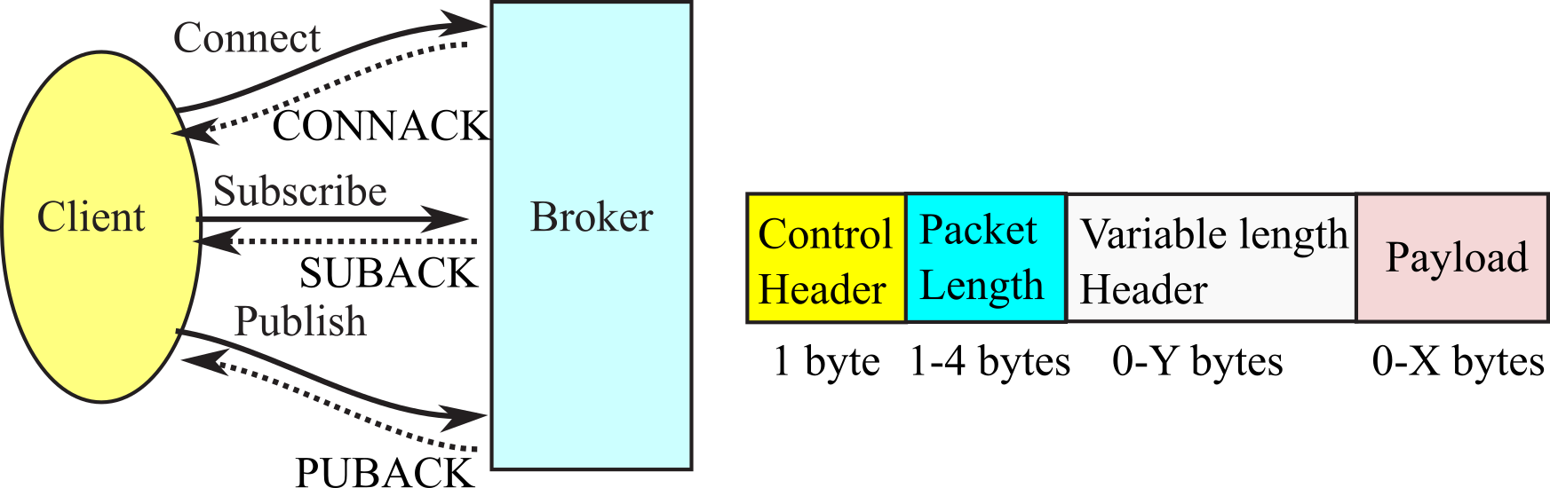
Figure 4.10.2. MQTT message flow initiated by the client and message packet format.
The broker does not normally store messages, so a consumer must be connected when the producer publishes new data. The downside of having an always-on connection is that it limits the amount of time the devices can be put to sleep. If the device mostly sleeps, then another MQTT protocol can be used: MQTT-SN, which is an extension of MQTT for sensor networks, originally designed to support ZigBee. MQTT-S is another extension that allows the use of UDP instead of TCP as the transport protocol, with support for peer-to-peer messaging and multicasting.
Program 4.10.1 shows the creation and transmission of a MQTT publication of variables A, B, C. It creates a JSON payload. In this code, UART5 is interfaced to the ESP8266. MODE is the publication name. Subscriptions are simple numbers 1,2,3.
static uint32_t bufpos = 0;
static uint32_t parse = 0;
char serial_buf[128];
uint32_t A,B,C; // data
void TM4C_to_MQTT(void){
char msp[24] = "";
sprintf(msp, "%d", MODE);
sprintf(msp + strlen(msp),",");
sprintf(msp + strlen(msp),"%d", A);
sprintf(msp + strlen(msp),",");
sprintf(msp + strlen(msp),"%d", B);
sprintf(msp + strlen(msp),",");
sprintf(msp + strlen(msp),"%d", C);
sprintf(msp + strlen(msp),","); // dangling comma to terminate CSV
UART5_OutString(msp);
UART5_OutChar('\n'); // Send NL to indicate EOT
}
void Parser(void) {
uint8_t cmd_num = atoi(w2b_cmd); // ASCII command to integer
if(cmd_num == 0x1) {
// Command #1
}
if (cmd_num == 0x2) {
// Command #2
}
if (cmd_num == 0x3) {
// Command #3
}
}
void MQTT_to_TM4C(void) {
parse = 0x0;
if((UART5_FR_R & UART5_FR_RXFE)==0){ // data??
input_char =(UART5_DR_R & 0xFF); // Read the data
if(input_char != '\n'){ // process if not newline
serial_buf[bufpos] = input_char;
bufpos++;
}
else {
serial_buf[bufpos] = ','; // Add a comma
bufpos++;
if(bufpos > 0) {
strcpy(w2b_cmd, strtok(serial_buf, ","));
parse = 1; // Parse incoming data
}
bufpos = 0; // Reset for next string
}
else{ // No new data in the RXD buffer -> Exit routine
}
}
if (parse == 1){
Parser();
}
}
Program 4.10.1. MQTT low level routines.
Another disadvantage of MQTT is the lack of encryption in the base protocol. MQTT was designed to be a lightweight protocol, and incorporating encryption would add a significant amount of overhead to the connection. One can, however, use Transport Layer Security (TLS) extensions to TCP, or add custom security at the application level. For more information, see
http://www.hivemq.com/blog/mqtt-essentials/
http://www.steves-internet-guide.com/mqtt-works/
4.11. Lab 4 MQTT
Lab 4 for this course can be downloaded from this link Lab04E.docx
Each lab also has a report Lab04EReport.docx
This work is based on the course ECE445L
taught at the University of Texas at Austin. This course was developed by Jonathan Valvano, Mark McDermott, and Bill Bard.
Reprinted with approval from Embedded Systems: Real-Time Interfacing to ARM Cortex-M Microcontrollers, ISBN-13: 978-1463590154

Embedded Systems: Real-Time Interfacing to ARM Cortex-M Microcontrollers by Jonathan Valvano is
licensed under a Creative
Commons
Attribution-NonCommercial-NoDerivatives 4.0 International License.