Lab
26
The aMAZing Traveler (Spring 2003)
The robot materials
were funded by a grant from Tivioli.
Ideas for EE345M Fall 2003 (send
your thoughts to my email at Jonathan W. Valvano):
1) line-tracker road
rally: follow a figure 8 track at a constant speed
2) find
and pick up light-colored balls, leaving the dark-colored balls
Goals
• Design a maze-traversing robot,
• Interface motors and sensors to the 6812,
• Implement pulse-width modulation,
• Write low-level device drivers for the motors and sensors,
• Develop a high-level control system,
• Use communication skills to work effectively as team.
The overall goal is to travel from one side of the maze to the other.
Four walls enclose the field, and obstacles will be placed at unknown positions
in the field. The robot will begin at an unknown angle with its back touching
the starting wall. The goal is traverse the field and touch the finishing wall
on the opposite side. Although speed is not of primary concern, your machine
will be given a finite amount of time to complete its task. The walls and
obstacles will be constructed from standard 2” by 4” boards, which are
actually about 8 cm high. The obstacles may be placed up against the wall or
each other. You are not allowed to move or go over the obstacles.
Figure 26.1. Mechanical diagram of the maze.
Each robot kit contains the following materials, donated by Tivioli
Amazon.com, Erector Special Edition
Anniversary Set, 643 pieces, $99.99 each
Case, DC motor, wheels, axles, drive belts, pulleys, large and small
metal pieces, many nuts and bolts
BG Micro, bgmicro.com,
Quantity 1, PWR1123, 5VDC/4A Switcher power supply, $6.49 each
Quantity 1, PWR1020, Computer Power Cord, $1.19 each
All Electronics Corporation, Phone 1-800-826-5432
Quantity 4, SPR-5, 0.19"D by 0.3" L SPRING, O.L.0.7",
$0.06 each
Quantity 1, CC-2, TWO CONDUCTOR COIL CORD, $0.55 each
Quantity 4, SMS-189, MINI-SNAP-ACTION SWITCH, $0.50 each
Jameco, 1-800-831-4242, www.jameco.com
Quantity 1, 162190, HNGH12-1324Y MOTOR GEAR 225RPM 12VDC, $10.95 each
12V (but will work at 5V), 65 mA, 225 RPM at 12V, torque 700g-cm, shaft
diameter 0.16in
Quantity 2, 163395, 5017-935, 30 ohm, 280 mA, 400 steps/rotation stepper
motor, $3.19 each
8.4V (but will work at 5V), detent torque 36g-cm, holding torque 791g-cm,
shaft diameter 0.155in
Quantity 1, 157067, 14500 RBT SERVO MOTOR & GEAR, $17.95 each
4.8 to 6V, torque 49 oz-in, speed 16 seconds to 60 degrees
Quantity 100, 42446, 6-32 STD machine screw, $0.016 each
Quantity 100, 42420, 6-32 STD hex nut, $0.012 each
Quantity 100, 106868, #6 lock washer, $0.012 each
Other materials available for checkout in ENS627 include
PWR1109, 6VDC/1A Power supply, $2.95 each (from BG Micro)
AIRPAXC42MO48A04 MOTOR STEP 5VDC/9.1ohm, $2.36 each
(from Jameco)
SPR-3, 0.4" DIA. by 3.65" SPRING, $0.15 each (from All
Electronics)
Electronics available for checkout on the second floor
IRF522, N CHANNEL MOSFET, drives up to 8A, $0.40 each
TIP120, NPN TO-220 DARLINGTON, $0.65 each
1N4004, RECT DIODE 1AMP/400PIV, $0.09 each
L293B, H-bridge driver, $1.15 each
HS-303
- Economy Standard Servo (http://www.brookshiresoftware.com/)
| Position
|
Pulse
Width
|
Example
Pulse
|
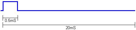
| Minimum
|
0.5ms
|
|
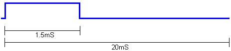
| Center
|
1.5ms
|
|
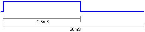
| Maximum
|
2.5ms
|
|
Figure
26.2. The timing constraints of the HS-303
servo (http://www.brookshiresoftware.com/).
 Servos are a popular mechanism to implement steering in robotics.
Ranging from micro servos with 15oz-in torque to powerful heavy-duty
sailboat servos, they all share several common characteristics. A servo is
essentially a positionable motor. The
servo "knows" two things: where it is (the actual position) and where
it wants to be (the desired position). When
the servo receives a position, it attempts to move the servo horn to the desired
position. The task of the servo,
then, is to make the actual position the desired position.
The first step to understanding how servos work is to understand how to
control them. All timing and
electrical characteristics described here have been experimentally determined
from a "HS-303 HiTec" servo. The servo is controlled by three wires:
ground (black), power (red), and command (yellow).
Power is usually between 4V and 6V and should be separate from system
power (as servos are electrically noisy). Even
small servos can draw over an amp under heavy load so the power supply should be
appropriately rated. Though not
recommended, servos may be driven to higher voltages to improve torque and speed
characteristics. Servos are commanded through "Pulse Width
Modulation," or PWM, signals sent through the command wire.
Essentially, the width of a pulse defines the position.
For example, sending a 1.5ms pulse to the servo, tells the servo that the
desired position is 90 degrees. In
order for the servo to hold this position, the command must be sent at about 50
Hz, or every 20 ms.
Servos are a popular mechanism to implement steering in robotics.
Ranging from micro servos with 15oz-in torque to powerful heavy-duty
sailboat servos, they all share several common characteristics. A servo is
essentially a positionable motor. The
servo "knows" two things: where it is (the actual position) and where
it wants to be (the desired position). When
the servo receives a position, it attempts to move the servo horn to the desired
position. The task of the servo,
then, is to make the actual position the desired position.
The first step to understanding how servos work is to understand how to
control them. All timing and
electrical characteristics described here have been experimentally determined
from a "HS-303 HiTec" servo. The servo is controlled by three wires:
ground (black), power (red), and command (yellow).
Power is usually between 4V and 6V and should be separate from system
power (as servos are electrically noisy). Even
small servos can draw over an amp under heavy load so the power supply should be
appropriately rated. Though not
recommended, servos may be driven to higher voltages to improve torque and speed
characteristics. Servos are commanded through "Pulse Width
Modulation," or PWM, signals sent through the command wire.
Essentially, the width of a pulse defines the position.
For example, sending a 1.5ms pulse to the servo, tells the servo that the
desired position is 90 degrees. In
order for the servo to hold this position, the command must be sent at about 50
Hz, or every 20 ms.
If you were to send a pulse longer than 2.5 ms or shorter than 0.5 ms,
the servo would attempt to overdrive (and possibly damage) itself. Once the
servo has received the desired position (via the PWM signal) the servo must
attempt to match the desired and actual positions. It does this by turning
a small, geared motor left or right. If, for example, the desired position
is less than the actual position, the servo will turn to the left. On the
other hand, if the desired position is greater than the actual position, the
servo will turn to the right. In
this manner, the servo "zeros-in" on the correct position.
Should a load force the servo horn to the right or left, the servo will attempt
to compensate. Note that there is no control mechanism for the speed of movement
and, for most servos, the speed is specified in degrees/second. Indeed,
one of the primary tasks of VSA
is to synthesize servo speed control by stepping through a series of positions.
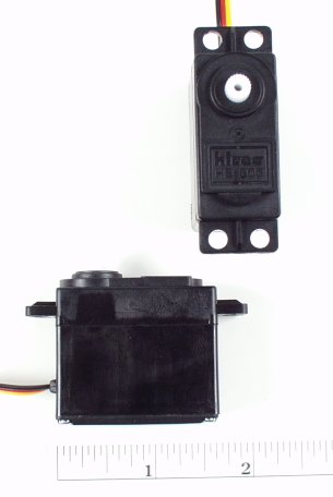
Figure 26.3. HS-303 servos(http://www.brookshiresoftware.com/).
| Operating Voltage
|
4.8V
|
|
6.0V
|
| Torque
|
42 oz-in
|
3.3 kg-cm
|
|
49 oz-in
|
3.7 kg-cm
|
| Speed @ 60 degrees
|
19
sec
|
|
15
sec
|
|
|
Standard
|
|
Metric
|
| Size L x W x H
|
1.6"
x 0.8" x 1.4"
|
|
41
x 20 x 37mm
|
| Weight
|
1.9
oz
|
|
48.5g
|
|
|
|
|
|
|
Table 26.1. HS-303 HiTec"
servo specifications (http://www.brookshiresoftware.com/).
For more information on servos, search the web site: http://www.brookshiresoftware.com/
26A. Preparation (this is due in class
April 2 and turn it in to Valvano)
1: Create a robot design team with 3 to 5 members. If you create a team with
just three members, you may be asked to include one more if the class gets down
to the end of the team selection process and we have one or two students without
a team. The members do not have to be in the same lab section or have the same
TA as the previous labs. The ideal team has at least one member with strengths
in the areas of mechanical design (e.g., pulleys, belts, motors, and
rack-and-pinion steering), electrical interfacing (e.g., transistors, currents,
back EMF, servo interfacing, and sensor interfacing), power management (e.g.,
maintaining constant +5V power to the 6812 while operating the motors), software
design (e.g., device drivers, juggling multiple time-critical tasks, making it
fit into 4K of ROM space), high-level control, and project management (e.g.,
conflict resolution, report generation, and keeping on schedule). Part of your
final project grade will be confidential peer evaluations, so choose your team
wisely, then make a commitment to get this project finished. Turn in to the
Valvano before Quiz 2:
first
and last names of all team members
home
phone numbers of all team members
email
addresses of all team members
select
at least two times each week for an official team project meeting (without the
TA)
list
all the regularly scheduled lab hours that it is possible for all your members
to meet weekly with a TA
We will select one of these hours to be when your preparation and
demonstrations will be due.
26A. Procedure (do this during your lab
period)
1: Design and build the mechanical aspects of the robot. It must move, turn,
carry the electronics, and recognize a collision. After a collision it should be
able to determine what it has hit: e.g., front wall, left wall, right wall, back
wall or obstacle. Make a rough mechanical sketch of the robot showing how it
moves, turns, carries, and senses. A detailed drawing will be required for the
final report, but at this time only a rough sketch is required. I.e., just
enough detail for the TA to understand your basic approach, but not enough
detail for someone to build a duplicate.
2: Design the electronic interface between the
steering and power motor(s) and the 6812. We expect you to use the 4A +5V
regulated supply to power the system, but you are free to develop other means to
power the system. Please test the circuitry before connecting to the 6812.
Snubber diodes must be used for all devices having an inductive load. Please
consider the required current when designing the interfaces. Use a multimeter to
measure the actual voltages and currents. Watch the +5V signal on the scope
during times when power is turned on and off to verify a constant power supply
line. Please thoroughly test all interfaces before connecting to the 6812.
3: Show how the system will be powered. Capacitors will be required to guarantee
a constant voltage to the 6812.
4: Design the low-level software drivers for the movement and steering motors.
5: Write a simple high-level main program to test the movement and
steering. Measure the maximum speed of the robot. Experimentally determine the
best way to make –90, -45, +45 and +90 degree turns. Calculate the accuracy of
the turning algorithm. I.e., if you say turn +90, how many degrees does it
actually turn?
26A.
Deliverables (exact components of the lab report)
A) Objectives (not required for this 26A)
B) Hardware Design
1)
Rough mechanical sketch of the robot (Section 1)
2)
Electrical circuit diagram for the motor interfaces (Section 2)
3)
Power supply circuitry (Section 3)
C) Software Design (printout of these software components)
1)
Low-level device drivers for the motor interfaces (header and code files)
(Section 4)
2)
High-level test program to evaluate movement and steering (Section 5)
D) Measurement Data
1)
Give the voltage and currents of each of the motors used (Section 2)
2)
Give the robot speed and turning accuracy (Section 5)
E) Analysis and Discussion
1)
Minutes (date, time, duration, attendance, topics) for each team meeting
26A. Checkout (show this to the TA)
You
should be able to demonstrate to the TA your robot moving forward, backward, and
turning –90, -45, +45 and +90 degrees.
26B. Preparation (do
this before your lab period)
1: Develop a high-level plan of how your
robot will traverse the field. Your
algorithm must involve abstractive methods. I.e., it must be layered, with a
high-level algorithm separated from the low-level details of how the machine
operates. A finite state machine like moore2.c
is one example of how this abstraction might be implemented. You are of course
allowed to develop your own approach, as long as there is a clear mapping from
the high-level algorithm to the eventual C code. For example, if you decide to
implement a finite state machine, write the state graph for the maze-traversing
algorithm.
2: Develop an initial data flow graph of the hardware-software system. Include
the motors, sensors, interface drivers, interrupt service routines, and
strategic global variables.
3: Develop an initial call graph of the software system. Include foreground
and background modules and their linkage (which ones call which).
4: Write the header file for the low-level sensor software driver.
26B. Procedure (do this during your lab
period)
1: Design the electronic interfaces connecting the sensors to the
6812. Again, please test the circuitry before connecting to the 6812.
2: Design the low-level software drivers for the sensors.
3: Write a second high-level main program to test the movement, steering and
sensors. This program should demonstrate most of the middle-level building
blocks that will be required for the high-level maze-tracking algorithm. Monitor
the power supply current during various operations
(stopped, moving and turning).
4. Experimentally verify the robot can determine into which object it has
collided.
26B.
Deliverables (exact components of the lab report)
A) Objectives (not required for this 26B)
B) Hardware Design
1)
Most recent electrical circuit diagram for the motor interfaces (26A Section 2)
2)
Most recent power supply circuitry (26A
Section 3)
3)
Electrical circuit diagram for the sensor interfaces (26B Section 1)
C) Software Design (printout of these software components)
1)
Low-level device drivers for the motor interfaces (header and code files) (26A
Section 4)
2)
Low-level device drivers for the sensor interfaces (header and code files) (26B
Section 2)
3)
High-level test program to evaluate movement, steering and sensing (26B Section
3)
D) Measurement Data
1)
Power supply current for various operations (26B Section 3).
2)
Accuracy of the object detection system (26B Section 4)
E) Analysis and Discussion
1)
Minutes (date, time, duration, attendance, topics) for each team meeting
2)
List of the remaining major problems to solve
26B. Checkout (show this to the TA)
You should
be able to demonstrate to the TA your robot moving forward, turning, and
detecting objects.
26C.
Preparation (do this before your lab period)
1: Write the C code for the
maze-traversing algorithm using abstractive methods. It should have a clear
mapping from the high-level algorithm to the C code.
2: Make detailed mechanical drawings of the robot showing how it moves, turns,
carries, and senses. There should be enough detail so the robot could be
duplicated.
26C. Procedure (do this during your lab
period)
1: Debug the high-level maze-traversing algorithm.
2: Draw the final data flow graph of the
hardware-software system. Include the motors, sensors, interface drivers,
interrupt service routines, and strategic global variables.
3: Draw the final call graph of the software system.
4. Run the robot al least five times and measure the success rate and the
elapsed time.
26C.
Deliverables (exact components of the lab report)
A) Objectives (1/2
page maximum)
B) Hardware Design
1)
Final mechanical drawing of the robot (26C preparation)
2)
Final electrical circuit diagram for the motor interfaces (26A Section 2)
3)
Final power supply circuitry (26A
Section 3)
4)
Final electrical circuit diagram for the sensor interfaces (26B Section 1)
C) Software Design (printout of these software components)
1)
Low-level device drivers for the motor interfaces (header and code files) (26A
Section 4)
2)
Low-level device drivers for the sensor interfaces (header and code files) (26B
Section 2)
3)
High-level algorithm to traverse the maze (26C Section 2)
4)
Final data flow graph
5)
Final call graph
D) Measurement Data
1)
Success rate and time to complete maze
E) Analysis and Discussion (1
page maximum)
F) Post-mortem concerning team member interactions (attached to the report)
1)
Each team member evaluates each other team member including oneself
Simply list one or two weaknesses.
Simply list two or three strength characteristics.
2)
Major failures in the way the team interacted (if any)
3)
Major successes in the way the team interacted
G) Peer Review (each student submits independently and confidentially directly
to the TA)
Classify
each team member including oneself as:
- worked harder than average (explain)
- worked an average amount
- worked less than average (explain)
26C. Checkout (show this to the TA)
You should
be able to demonstrate to the TA your robot traversing the maze.