Chapter
3. Introduction to
Electronics
Embedded Systems - Shape The World
Jonathan Valvano and Ramesh Yerraballi
This chapter introduces electronics. We will learn Ohm’s Law. This chapter is foundational, laying the ground work for the remainder of the book.
|
Learning Objectives:
|
Video 3.0. Introduction to Circuit Analysis |
3.0. Introduction
Most students reading this will have had some prior training in electronics. However, this brief section will provide an overview of the electronics needed to understand electric circuits in this class. Current, I, is defined as the movement of electrons. In particular, 1 ampere (A) of current is 6.241×10¹⁸ electrons per second, or one coulomb per second. Current is measured at one point as the number of electrons travelling per second. Current has an amplitude and a direction. Because electrons are negatively charged, if the electrons are moving to the left, we define current as flowing to the right. Voltage, V, is an electrical term representing the potential difference between two points. The units of voltage are volts (V), and it is always measured as a difference. Voltage is the electromotive force or potential to produce current. We will see two types of conducting media: a wire and a resistor. Wires, made from copper, will allow current to freely flow, but forcing current to flow through a resistor will require energy. The electrical property of a resistor is resistance in ohms (Ω). Ideally, a wire is simply a resistor with a resistance of 0 Ω. The basic relation between voltage, current, and resistance for a resistor is known as Ohm’s Law, which can be written three ways:
V = I * R Voltage = Current * Resistance
I = V / R Current = Voltage / Resistance
R = V / I Resistance = Voltage / Current
Video 3.1. Circuit Basics
The left side of Figure 3.1 shows a circuit element representation of a resistor, of resistance R. Whenever we define voltage, we must clearly specify the two points across which the potential is defined. Typically we label voltages with + and –, defining the voltage V as the potential to produce current from the + down to the –. When defining current we draw an arrow signifying the direction of the current. If the voltage V is positive, then the current I will be positive meaning the current is down in this figure. However, because electrons have negative charge, the electrons are actually flowing up. According to the passive sign convention, we define positive current as the direction of the flow of positive charge (or the opposite direction of the flow of negative charge). The middle of Figure 3.1 shows a circuit with a 1 kΩ resistor placed across a 3.7V battery. 1 kΩ exactly the same as 1000 Ω, just like 1 km is the same as 1000 m. According to Ohm’s Law, 3.7 mA of current will flow down across the resistor. 1 mA exactly the same as 0.001 A, just like 1 mm is the same as 0.001 m. In this circuit, current flows clockwise from the + terminal of the battery, down across the resistor, and then back to the – terminal of the battery.
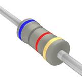
Figure 3.1. The voltage and current definitions; a circuit with a battery; and a drawing of a resistor.
: There is 1 V across a resistor, and 5 mA is flowing. What is the resistance?
: There is 2 V across a 100Ω resistor. How much current is flowing?
: What happens if you place a wire directly from + terminal to the –terminal of a battery?
There are two analogous physical scenarios that might help you understand the concept of voltage, current, and resistance. The first analogy is flowing water through a pipe. We place a large reservoir of water in a tower, connect the water through a pipe, and attach a faucet at the bottom of the pipe, see Figure 3.2. In this case pressure is analogous to voltage, water flow is analogous to current, and fluid resistance of the faucet is analogous to electrical resistance. Notice that water pressure is defined as the potential to cause water to flow, and it is measured between two places. Pressure has a polarity and water flow has a direction. If the faucet is turned all the way off, its resistance is infinite, and no water flows. If the faucet is turned all the way on, its resistance is not zero, but some finite amount. As we turn the faucet we are varying the fluid resistance. The fluid resistance will determine the amount of flow:
Flow = Pressure/Resistance
Figure 3.2. Three analogous physical systems demonstrating Ohm’s Law.
: If pressure is measured in Newtons/m2 (Pascal) and flow measured in m3/sec, what are the units of fluid resistance?
A second analogy is heat flow across a solid. If we generate a temperature gradient across a solid, heat will flow from the hot side to the cold side (right side of Figure 3.2). This solid could be a glass window on a house or the wall of your coffee cup. In this case temperature gradient is analogous to voltage, heat flow is analogous to current, and thermal resistance of the solid is analogous to electrical resistance. Notice that potential is defined as the temperature difference between two places. Heat flow also has a direction. If the coffee cup is made from metal, its thermal resistance is low, lots of heat will flow, and the coffee cools off quickly. If the coffee cup is made of Styrofoam, its resistance is high, little heat will flow, and the coffee remains hot for a long time. The temperature difference divided by the thermal resistance will determine the amount of flow:
Flow = (T1-T2)/Resistance
: If heat flow is measured in watts (Joules/sec) and temperature measured in ºC, what are the units of thermal resistance?
The R-value of insulation put in the walls and ceiling of a house is usually given in units per square area, e.g., m2∙ºC/W. The amount of heat flow across a wall is:
Flow = Area * (T1-T2)/R-value
Another important parameter occurring when current flows through a resistor is power. The power (P in watts) dissipated in a resistor can be calculated from voltage (V in volts), current (I in amps), and resistance (R in ohms). Interestingly, although voltage has a polarity (+ and –) and current has a direction, power has neither a polarity nor a direction.
P = V * I Power = Voltage * Current
P = V2 / R Power = Voltage2 / Resistance
P = I2 * R Power = Current2 * Resistance
: There is 1 V across a resistor, and 5 mA is flowing. How much power is being dissipated?
: There is 2 V across a 100Ω resistor. How much power is being dissipated?
The energy (E in joules) stored in a battery can be calculated from voltage (V in volts), current (I in amps), and time (t in seconds). In a manner similar to power, energy has neither a polarity nor a direction.
E = V * I * t Energy = Voltage * Current * time
E = P * t Energy = Power * time
Video 3.2. Batteries, Power and Energy
3.1. Electric Circuits
A switch is an element used to modify the behavior of the circuit (Figure 3.3). If the switch is pressed, its resistance is 0, and current can flow across the switch. If the switch is not pressed, its resistance is infinite, and no current will flow. In reality, the ON-resistance of a switch is less than 0.1Ω, but this is so close to zero, we can assume the ideal value of 0 in most cases. Similarly, the OFF-resistance is actually greater than 100MΩ, but this is so close to infinity that we can again assume the ideal value of infinity. The classic electrical circuit involves a battery, a light bulb (modeled in this circuit as a 100Ω resistor), and a switch.
Figure 3.3. When the switch is open, no current can flow, and the bulb does not emit light. When the switch is closed, 90 mA of current will flow, and the bulb emits light.
: If the switch is on, how much power is being dissipated in the bulb?
: If the battery has 1000 joules stored in it, how long will the light be illuminated, assuming the voltage is constant?
There are a few basic rules that allow us to solve for voltages and currents within a circuit comprised with batteries, switches, and resistors.
Current always flows in a loop. In Figure 3.3 when the switch is pressed, current flows out of the + side of battery, across the switch, through the light and back to the – side of the battery. When there is no loop, no current can flow. In Figure 3.3 when the switch is off, the loop is broken, and no current will flow.
Kirchhoff's Voltage Law (KVL). The sum of the voltages around the loop is zero. For a battery, we label the + and – sides exactly the way the battery is labeled. For a resistor, we label the current arrow and the voltage + – like the left side of Figure 3.1. The important step is the direction of the current arrow must match the polarity of the corresponding voltage. It is common practice to draw arrows in the direction the currents actually flow, so the voltages will be positive. However, sometimes we don’t know which way the current will flow, so we can just guess. If we happen to guess wrong, both the current and voltage will calculate to be negative and the correct behavior will still be obtained. We can think of the switch as a resistor of either 0 or infinity resistance, so it too can be labeled with a current arrow and a voltage polarity. Figure 3.4 shows the light circuit redrawn to show voltages and currents. As we are going around a circle and pass from + to –, we add that voltage. However, if we pass across an element from – to + we subtract that voltage.
Figure 3.4. The voltages around a loop will sum to zero (KVL).
Kirchhoff's Current Law (KCL). The sum of the currents into a node equal the sum of the currents leaving a node as shown in Figure 3.5. To solve circuits using KCL and KVL, the current arrow across a resistor goes from the + voltage to the – voltage. Conversely, the current arrow across a battery goes from the – voltage to the + voltage. This is the same thing as saying current comes out of the battery’s + terminal and into the battery’s – terminal. At Node A, there is one incoming current and one outgoing current. This is a simple but important fact that I1 = I2. At Node B, there is one incoming current and two outgoing currents. Therefore, I3 = I4+I5. There are two currents into NodeC and two currents out of NodeC; thus, I6+I7 = I8+I9.
Figure 3.5. The sum of the currents into a node will equal the sum of the currents leaving (KCL).
Observation: If at all possible, draw the circuit so current flows down across the resistors and switches. As a secondary rule have currents go left to right across resistors and switches.
Video 3.3Voltage and Current Division
Series resistance. If resistor R1 is in series with resistor R2, this combination behaves like one resistor with a value equal to R1+R2. See Figure 3.6. This means if replace the two series resistors in a circuit with one resistor at R= R1+R2, the behavior will be the same. The V equals V1+V2. By KCL, the currents through the two resistors are the same. These two facts can be used to derive the voltage divider rule
V2 = I*R2 = (V/R)*R2 = V*R2/(R1+R2)
Figure 3.6. The series combination of two resistors, R1 R2, is equivalent to one resistor at R1+R2.
: Using Figure 3.6, assume I is 1mA, R1 is 2kΩ and R2 is 3kΩ, what is V?
: Using Figure 3.6, assume V is 10V, R1 is 2kΩ and R2 is 3kΩ, what is V2?
Parallel resistance. If resistor R1 is in parallel with resistor R2, this combination behaves like one resistor with a value equal to
See Figure 3.7. This means we can replace the two parallel resistors in a circuit with one resistor at R= R1*R2/(R1+R2). The voltages across R1 and R2 will be the same because of KVL. Due to KCL, I=I1+I2. These facts can be used to derive the current divider rule
I1 = V/R1= (I*R)/R1 = I*(R1*R2/(R1+R2))/R1 = I*R2/(R1+R2)
I2 = V/R2= (I*R)/R2 = I*(R1*R2/(R1+R2))/R2 = I*R1/(R1+R2)
I = I1+I2
Figure 3.7. The parallel combination of two resistors, R1 R2, is equivalent to one resistor at R1*R2/(R1+R2).
: Using Figure 3.7, assume I is 1mA, R1 is 2kΩ and R2 is 4kΩ, what is V?
: Using Figure 3.7, assume V is 10V, R1 is 2kΩ and R2 is 4kΩ, what is I2?
3.2. Chapter 3 Quiz
3.1 Make this a matching definition with the word
a) Voltage ----------------------------------------------------- an electrical potential.
b) Current ----------------------------------------------------- the flow of charge (electrons)
c) Power ----------------------------------------------------- the rate of energy change.
d) Energy ----------------------------------------------------- defines the amount of work that can be done
e) Resistance ----------------------------------------------------- potential divided by flow
3.2 Make this a matching definition with the word
a) Ohm's Law .----------------------------- Voltage equals current times resistance
b) Kirchhoff's Current Law (KCL).----------------------------- The sum of the currents into a node equal the sum of the currents leaving a node
c) Kirchhoff's Voltage Law (KVL). ----------------------------- The sum of the voltages around the loop is zero.
3.3 Know the formula (multiple choice for each)
a) Voltage current power .----------------------------- P = V*I
b) Energy voltage current time.----------------------------- E = V*I*time
c) Power voltage resistance. ----------------------------- P = V2/R.
3.4 Fill in this table with the equivalent resistance (all values are in ohms)
|
R1 |
R2 |
R1 in series with R2 |
R1 in parallel with R2 |
|
1000 |
4000 |
|
|
|
1000 |
9000 |
|
|
|
1000 |
|
5000 |
|
|
1000 |
|
|
750 |
|
|
|
4000 |
1000 |
3.5 2 V is applied across the parallel combination of a 1000Ω and a 4000Ω resistor. What is the voltage across the 4000Ω resistor? What is the current through the 4000Ω resistor?
3.6 Consider this 3-bit digital to analog converter. We define the logic state of each switch as 0 or 1, where 0 means not pushed and 1 means pushed. Define a 3-bit number n (0 to 7) which specifies the three switch positions. n = 0 means none are pushed. n = 1 means Sw0 is pushed. n = 2 means Sw1 is pushed. n = 3 means Sw1 and Sw0 are pushed. n = 4 means Sw2 is pushed. n = 5 means Sw2 and Sw0 are pushed. n = 6 means Sw2 and Sw1 are pushed. n = 7 means all are pushed. Derive a relationship between the current I and the number n. Multiple choice
a) I = 0
b) I = n*20mA (answer)
c) I = n2+10mA
d) I = 140 mA
e) none of the above
Reprinted with approval from Embedded Systems: Introduction to ARM Cortex-M Microcontrollers, 2014, ISBN: 978-1477508992, http://users.ece.utexas.edu/~valvano/arm/outline1.htm
