Chapter 6: Device driver, Local variables, and LCD output
Jonathan Valvano and Ramesh Yerraballi
In this chapter we will learn how to allocate local variables on the stack. Variables are an important concept in programming. Scope defines where in the software a variable can be accessed. Allocation defines how the variable is implemented. If the variable needs to be permanent, it will be allocated in RAM permanently. If the variable is temporary, we can allocate it in a register or on the stack temporarily.
The second objective of this chapter is to interface an LCD to the microcontroller and write a set of functions to output numbers and strings to the display. We will use fixed-point numbers to specify non-integer values using integer math. We will introduce recursion as a software design technique.
Table of Contents:
- 6.1.
Interface, Implementation, and Invocations of Functions
- 6.2.
Local Variables
- 6.3.
Stack frames
- 6.4. Linking C to assembly
- 6.5. Serial Peripheral Interface (SPI)
- 6.6. ST7735R Interfacing
- 6.7.
Fixed-point Numbers
- 6.8.
Floating-point Numbers
- 6.9.
Numerical Output
- 6.10.
printf
- 6.11.
Lab 6. LCD Device Driver for the Sitronix ST7735
Video 6.0. Introduction to Chapter 6, and ECE319K Lab 6.
6.1. Interface, Implementation, and Invocations of Functions
Before discussing local variables, let's review functions. Designing modular code is the process of breaking a complex problem into small pieces and then building the system from by combining the pieces in a stategeic way. Functional abstraction is separating "what the function does" from "how the function works". A software module has three parts. We call this the three I's
The interface is a header file with prototypes for the public functions of the module
The implementation is a code file with definitions for the public and private functions of the module
The invocation is a higher-level file with software that calls public functions of the module
Video 6.1.1. Modular approach to software development.
An invocation is where the function is called. The caller establishes the input parameters and executes a BL to the function. Prototype, interface, and declaration are three names for the same thing. It defines the function name and the number/types of the input/output parameters. The definition or implementation the actual code that will be executed. In general, The function invocations exist at a higher level than the definitions. Typically, the function prototypes or declarations are in a header file, and the function definitions are in a code file. The video outlines this modular approach to software development Program 6.1.1 shows the main.c file, which includes the function invocations. Program 6.1.2 shows the Logger.c file, which includes the function definitions. Program 6.1.3 shows the Logger.h file, which includes the function declarations..
// main.c
#include "UART.h"
#include "random.h"
#include "Logger.h"
// Global Variables in RAM
char *progtitle="Histogram of Randoms"; // Global Scope and
// Permanent persistence (RAM)
// The entry point is a function with global scope
int main(){
uint32_t i; // Local scope (in main) and persists
// as long as main does does not return
// allocated on the Stack
Output_Init();
Random_Init(1317); // Initialize the Random Number
Generator
for (i=0; i < 10000; i++){
uint32_t val; // Local scope (for loop), and
persists
// while the for loop runs
// allocated on the Stack
val = Random()%MAXVAL;
Logger_track(val);
}
Logger_display();
while(1);
}
Program 6.1.1. The main.c file used in the above video.
// Logger.c
// Keeps track of the frequencies of values in a local array
// and displays them like a histogram when requested
#include <stdio.h>
#include "Logger.h"
#define LineWidth 40
static uint8_t Frequency[MAXVAL]; // Local scope (to file Logger.c)
// permanent
persistence (RAM)
extern char *progtitle;
static void pretty_print(uint8_t, uint8_t); //Prototype
static void LogInit(){
uint8_t i; // Local scope (in LogInit) and persists
// as long as LogInit does does not return;
// allocated on the Stack
for (i=0; i < MAXVAL; i++)
Frequency[i]=0;
}
// Keeps track of values on successive calls
// in the Log array
uint8_t Logger_track(uint32_t val){
static uint8_t first=0; // Local (in Logger_track)
// permanent persistence (RAM)
if(first == 0){
LogInit();
first=1;
}
if(val > MAXVAL) return(0); // Error check - fail
Frequency[val]++; // Increment frequency of the value
return(1); //success
}
void Logger_display(){
uint8_t index;
printf("%s\n",progtitle);
for (index=0; index< MAXVAL; index++){
pretty_print(index,Frequency[index]);
}
}
// Local (to file) static function that can only be called from
// within this file
static void pretty_print(uint8_t val, uint8_t times){
uint8_t i;
printf("%d:",val);
for(i=0; i < times; i++){
if (i >= LineWidth) break;
printf("*");
}
printf("%d\n",times);
}
Program 6.1.2. The Logger.c code file used in the above video.
// Logger.h
#define MAXVAL 256
uint8_t Logger_track(uint32_t val); // log val
void Logger_display(); // display the data
Program 6.1.3. The Logger.h header file used in the above video.
:What does the static means in "static uint8_t Frequency[MAXVAL]"?
:What does the extern mean in "extern char *progtitle"?
: What does the static means in "static void LogInit()"?
: What does the static means in "static uint8_t first=0"?
: Why does pretty_print have a prototype, but LogInit does not?
6.2. Local Variables
Variables are an important component of software design, and there are many factors to consider when creating variables. Some of the obvious considerations are the size and format of the data. In this class we will consider integers, which can be 8-bit, 16-bit or 32 bits. Furthermore, integers can signed or unsigned. Table 6.2.1 shows the C99 type definitions.
Precision |
Unsigned |
Signed |
|---|---|---|
8 bits |
uint8_t | int8_t |
16 bits |
uint16_t | int16_t |
32 bits |
uint32_t | int32_t |
Table 6.2.1. C99 type definitions for integers.
Another factor is the scope of a variable. The scope of a variable defines which software modules can access the data. Variables with an access that is restricted less than everywhere are classified as private, and variables shared between multiple modules are public. In general, a system is easier to design (because the modules are smaller and simpler), easier to change (because code can be reused), and easier to verify (because interactions between modules are well-defined) when we limit the scope of our variables. However, since modules are not completely independent we need a mechanism to transfer information from one to another. The ARM Application Binary Interface (ABI) has detailed descriptions of how to develop software interfaces. However, in this chapter, we will discuss the fundamentals of software interfaces.
An addition consideration for variables is allocation
or persistence. We could place variables in registers temporarily,
on the stack in RAM temporarily, in RAM permanently, or in ROM
permanently. We will use the terms allocated permanently and permanent
persistence to mean the same thing, created at compile time and never
destroyed. Because their contents are allowed to change, all variables
must be allocated in registers or RAM and not ROM. Constants can be placed
in ROM. A local variable has reduced scope and temporary
allocation. We can allocate a local variable in a register or on the
stack. One of the important objectives of this chapter is to present
design steps for creating, using, and destroying local variables on the
stack. In C, we create a local variable by defining it within the
function. We will consider parameters passed into or out of a function as
local variables, because they have reduced scope and temporary allocation.
The scope of the variable sum is within the entire
function, whereas the scope of i is within the
for-loop. Local variables are not initialized. Therefore it is your
responsibility to initialize your local variables.
While reading the following examples, notice the scope and allocation of the different variables. There are two
separate variables called num.
Variable |
Classification |
Scope |
Allocation |
|---|---|---|---|
sum |
local |
MyFunction |
stack or register |
i |
local |
for-loop |
stack or register |
TotalCount |
static |
that file |
RAM |
num |
static |
MyFunction2 |
RAM |
num |
static |
MyFunction3 |
RAM |
flag |
global |
everywhere |
RAM |
Table 6.2.2. Scope and allocation
uint32_t MyFunction(void){uint32_t sum;
sum = 0;
for(uint32_t i=0; i < 10; i++){
sum=sum+i;
}
return sum;
}
A static variable has reduced scope and
permanent persistence. The compiler allocates static variables in permanent RAM. The
scope can be reduced to a single function or a single file. Static
variables will be initialized to 0 on software reset, or we can explicitly
initialize it. It is good programming practice to initialize all your
varaibles, even if the compiler does initialize them to 0. Static
variables are initialized just once, at reset. In this example TotalCount
is initialized once to 0, it is shared within the file, so accessible to
both functions. TotalCount contains the total number
of times either function has been called. There are two copies of Num,
one for each function. The static Num variable
maintains the number of times each function has been called. The two
functions will return 1 if that function has been called more than 75
times or if the sum of the two calls is more than 100.
static uint32_t TotalCount=0;
uint32_t MyFunction2(void){
static uint32_t Num=0;
Num++; TotalCount++;
if((Num > 75)||(Count > 100)){
return 1; }
return 0;
}
uint32_t MyFunction3(void){
static uint32_t Num=0;
Num++; TotalCount++;
if((Num > 75)||(Count > 100)){
return 1; }
return 0;
}
A global variable has public scope and
permanent persistence. Public scope means any software in the system has
access to the variable. Global variables are permanently allocated in RAM.
Global variables will be initialized to 0 on software reset, unless we can
explicitly initialize it to something else. We will consider I/O port
registers as global variables, because they have public scope and
permanent persistence. The global variable Flag can
be accessed by both MyFunction4 and MyFunction5,
even if the functions are in different files. The extern
definition does not create a second copy of the variable, rather, it
provides access to the single shared global. Assume Flag and MyFunction4 are in one file.
uint32_t Flag;
void MyFunction4(void){
Flag = 0;
}
Assume MyFunction5 is in a different file than Flag and MyFunction4.
extern uint32_t Flag;
void MyFunction5(void){
Flag = 1;
}
Observation: It is poor programming style to use extern because it creates difficult to manage coupling between two modules.
In general, the qualifier const added to a
variable definition means the software cannot change its value. In
embedded systems with RAM and ROM, const added to a global
variable means it will be allocated in ROM permanently (permanent
persistence). The global constant Size can be
accessed anywhere in the software system, but cannot be dynamically
changed.
const uint32_t Size=100;
void MyFunction6(void){
for(uint32_t i=0; i < Size; i++){
// stuff
}
}
When the qualifier const added to a
parameter it means the software cannot change its value within the
function. The parameter Size can be accessed in the
function, but cannot be dynamically changed. In this example, the
parameter Size is still passed in Register R0, with
temporary allocation and private scope.
void MyFunction7(const uint32_t Size){
for(uint32_t i=0; i < Size; i++){
// stuff
}
}
A static function has reduced scope. On an
embedded system, all functions are permanentally allocated in ROM. If we
add static to a function definition, the scope can be reduced to
file in which it is defined. This means only functions also defined in
this file can call it. Other names for reduced scope functions are private
functions and helper functions. In general, it is good
design to reduce scope of data and functions as much as possible.
Prototypes for public functions are placed in the header file,
whereas prototypes for static functions are not placed in the
header file. This way we can separate what a module does (by calling public
functions) from how it works (implementation of all functions
including static functions). In the following example, the
function rand is static, so it is callable only within the
file. On the other hand, the function Random is
public and can be called from anywhere.
uint32_t static M=1;
uint32_t static rand(void){
M = 1664525*M+1013904223;
return(M);
}
uint8_t Random(void){
return(rand()>>24);
}
: How do you create a local variable in C?
: How do you create a global variable in C?
: Considering scope and allocation, what changes and what doesn't change when you add static to an otherwise global variable?
: Considering scope and allocation, what doesn't change when you add static to an otherwise local variable?
: Considering scope and allocation, what changes and what doesn't change when you add const to an otherwise global variable?
: Considering scope and allocation, what changes and what doesn't change when you add const to a function parameter?
The following video presents the implementation of local variables on the stack using SP-relative addressing
Program 6.2.1 shows the sum.c file used in the video. Program 6.2.2 shows the main.s file.
//------------Sum------------
// Input: num is a 32-bit unsigned int
// Output: Is the sum: 1+2+...+num
// Here is the C code
uint32_t Sum (uint32_t num){
uint32_t i, result=0;
for (i=1; i <= num; i++){
result += i;
}
return(result);
}
Program 6.2.1. The sum.c file used in the above video.
.text
.align 2
.global main
main:
// Call the non-recursive implementation with locals on stack
MOVS R0, #10
BL Sum // R0 should return as 55: 1+2+3...+10
Loop: B Loop // Loop forever
//------------Sum------------
// Input: R0 has input number (num)
// Output: R0 has the output which is the sum: 1+2+...+num
// Here is the Assembly Code
.equ i,0 // *Binding*: Local variable i is at offset 0 w.r.t SP
.equ result,4 // Local variable result is at offset 0 w.r.t SP
Sum:
PUSH {R4,R5,LR} // push things we will use for
scratch
SUB SP,#8 // *Allocation*: Allocate space for
// 2 local variables
both 32-bit
MOVS R4, #0
STR R4,[SP,#result] // *Access* Initialize
Result on stack
MOVS R4, #1
STR R4,[SP,#i] // *Access*
Initialize index i on stack
LoopS:
LDR R4,[SP,#i] // *Access*
load i into R4 from Stack
CMP R4,R0
BHI DoneS
LDR R5,[SP,#result] // *Access* load result
into R5 from Stack
ADDS
R5,R4 //
Result = Result + i;
STR R5,[SP,#result] // *Access* store result
from R5 to Stack
ADDS R4,#1 // i++
STR R4,[SP,#i] //
*Access* store i from R5 to Stack
B LoopS
DoneS
LDR R0,[SP,#result] // *Access* load Result in
R0 from Stack
ADD
SP,#8 //
*DeAllocation* Deallocate space for locals
POP {R4,R5,PC} //
Restore scratched registers and set pushed
// LR to PC to return
Program 6.2.2. The main.s file used in the above video. This is Cortex M0 code.
Video 6.2.2. Debugging Locals in assembly.***needs recording***
The following assembly code shows the PUSH and POP
instructions can be used to store temporary information on the stack. If a
subroutine modifies a register, it is a matter of programmer style as to
whether or not it should save and restore the register. According to AAPCS
a subroutine can freely change R0,R1,R2,R3 and R12, but the
subroutine must save and restore any other register it changes. In
particular, if one subroutine calls another subroutine, then it must save
and restore the LR. In the following example, assume the function modifies
Register R0, R4, R7 and calls another function. The programming style
dictates registers R4, R7, and LR be saved. Notice the return address is
pushed on the stack as LR but popped off into PC. When multiple registers
are pushed or popped, the data exist in memory with the lowest numbered
register using the lowest memory address. In other words, the registers in
the {} can be specified in any order, but the order in which they appear
on the stack is fixed according to the rule
"the smaller register number will be at the smaller memory address".
Of course, remember to balance the stack by having the
same number of pops as pushes.
Func: PUSH {R4,R5,R7,LR} // save registers as needed
// 1) allocate local variables
// 2) body of the function, access local
variables
// 3) deallocate local variables
POP {R4,R5,R7,PC} // restore registers and
return
The ARM processor has a lot of registers, and we appropriately should use them for temporary information such as function parameters and local variables. However, when there are a lot of parameters or local variables, we can place them on the stack. Program 6.2.3 has a large data buffer that is private to this function. It is inconvenient to store arrays in registers. Rather it is appropriate to place the array in memory and use indexed addressing mode to access the information. Because this buffer is private and temporary we will place it on the stack. 1) The SUB instruction allocates 10 32-bit words on the stack. Figure 6.2.1 shows the stack before and after the allocation. 2) During the execution of the function, the SP points to the first location of data. The local variable i is held in R0. R1 will contain i*4 as an offset into the buffer, because each buffer entry is 4 bytes. R2 will be SP+4*i. The addressing mode [R2] accesses data on the stack without pushing or popping. 3) The ADD instruction deallocates the local variable, balancing the stack.
|
Set: SUB SP,SP,#40 // 1)allocate 10
words |
// C language implementation |
Program 6.2.3. Allocation of a local array on the stack.
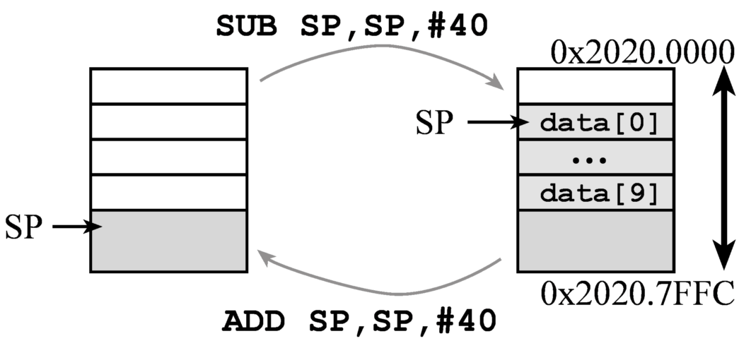
Figure 6.2.1. Allocation of a local array on the stack.
Stack implementation of local variables has four
stages: binding, allocation, access, and deallocation. In this section,
the software will create two local variables called sum and i.
1. Binding is the assignment of the address (not value) to a
symbolic name. In other words, we assign offsets for the variables. In
general, we perform binding by drawing a stack picture and deciding the
order of the local variables, see Figure 6.2.2. The symbolic name will be
used by the programmer when referring to the local variable. The assembler
binds the symbolic name to a stack index, and the computer calculates the
physical location during execution. In the following example, the local
variable sum will be at address SP+0, and the programmer
will access the variable using [SP,#sum] addressing. Similarly,
the local variable i will be at address SP+4, and the
programmer will access the variable using [SP,#i] addressing:
.equ sum,0 // 32-bit local variable, stored on the
stack
.equ i,4 // 32-bit local variable,
stored on the stack
2. Allocation is the generation of memory storage for the local variable, or assigning space. The computer allocates space during execution by decrementing the SP. In this first example, the software allocates the local variable by pushing a register on the stack. The variable sum is initialized to 0 and the variable i is initialized to 16. According to AAPCS, we must allocate space in multiples of 8 bytes. The contents of the register become the initial value of the variable.
MOVS R0,#0
MOVS R1,#16
PUSH {R0,R1} // allocate and initialize two
32-bit variables
Rather than creating local variables with initialization, the software could allocate the local variables by decrementing the stack pointer. Allocating locals this way creates them uninitialized. This method is most general, allowing the allocation of an arbitrary amount of data.
SUB SP,#8 // allocate two 32-bit variables
3. The access to a local variable is a read or write operation that occurs during execution. Because we use SP addressing with offset, we will only use LDR and STR to access local variables on the stack. In the first code fragment, we will add the contents of i to the local variable sum.
LDR R0,[SP,#i] // R0=i
LDR R1,[SP,#sum] // R1=sum
ADDS
R1,R0 // R1=i+sum
STR R1,[SP,#sum] // sum=i+sum
In the next code fragment, the local variable sum is divided by 16.
LDR R0,[SP,#sum] // R0=sum
LSRS R0,R0,#4
STR R0,[SP,#sum] // sum=sum/16
4. Deallocation is the release of memory storage for the location variable. This step frees up space. The computer deallocates space during execution by incrementing SP. The software deallocates two local variables by incrementing the stack pointer. When deallocating, we must balance the stack. I.e., we add to the SP exactly the same number as we decremented during allocation.
ADD SP,#8 // deallocate sum

Figure 6.2.2. Allocation of two local variables on the stack.
Program 6.2.4 shows a C and assembly function implementing the same function. This assembly implementation uses the PUSH instruction to allocate and initialize the local variables.
|
Calculate: |
// C language implementation |
Program 6.2.4. Allocation of two local variables on the stack.
: Write code that allocates four 32-bit local variables, uninitialized.
: Write code that binds four 32-bit local variables to the names a,b,c,d such that a is on top.
: Assuming the name of a 32-bit local variable is b, write code that sets b to 5.
: Write code that deallocates four 32-bit local variables.
: Assume Register R0 contains the size in 32-bit words of an array, determined at run-time. Write assembly code to allocate the array on the stack.
6.3. Stack frames
Each time a function is called a stack frame is created. There are four types of data that may be saved in the stack frame. By convention, if there are more than 4 input parameters, additional parameters above 4 will be pushed on the stack by the calling program. If the function calls another function, the LR (return address) must be pushed on the stack. By convention if the function uses registers R4–R11, it will push them on the stack so their values are preserved. Lastly, the function may allocate local variables on the stack.
Video 6.3.1. Local variables using a stack frame.
Each time a function is called a stack frame is created. There are four types of data that may be saved in the stack frame. By convention, if there are more than 4 input parameters, additional parameters above 4 will be pushed on the stack by the calling program. If the function calls another function, the LR (return address) must be pushed on the stack. By convention if the function uses registers R4–R11, it will push them on the stack so their values are preserved. Lastly, the function may allocate local variables on the stack.
One limitation of SP indexed addressing mode to access local variables is the difficulty of pushing additional data onto the stack during the execution of the function. In particular, if the body of the function pushes additional items on the stack, the symbolic binding becomes incorrect. There are two approaches to this problem. First, we could recompute the binding after each stack push/pop. Second, we could assign a second register to point into the stack, called a stack frame pointer. To employ a stack frame pointer, we execute the initial steps of the function: saving LR, saving registers, and allocating local variables on the stack. Once these initial steps are complete, we set another register to point into the stack. It's called a stack frame because all the local variables are allocated on the stack and will remain in this fixed position for the rest of the executing function. Because R4–R7 will be saved and restored, if we call another function, any of these would be appropriate for the stack frame pointer. E.g.,
MOV
R7,SP
We will not consider using R8-R11 as stack frame pointers on the Cortex M0, because these registers cannot be used for indexed mode addressing.
Observation Many processors have a standard specifying which register should be used for the stack frame pointer. On the x86, the EBP register will be used. The Apple Silicon M1 (ARM64) mandates register X29 as the stack frame pointer. On the Cortex M, there is no mandate to use a specific register as the stack frame pointer.
This stack frame pointer (R7) points to the local variables and parameters of the function. It is important in this implementation that once the stack frame pointer is established (e.g., using the MOV R7,SP instruction), that the stack frame register (R7) not be modified. The term frame refers to the fact that the pointer value is fixed. If R7 is a fixed pointer to the set of local variables, then a fixed binding (using the .equ pseudo op) can be established between Register R7 and the local variables and parameters, even if additional information is pushed on the stack. Because the stack frame pointer should not be modified, every subroutine will save the old stack frame pointer of the function that called the subroutine and restore it before returning. Local variable access uses indexed addressing mode using Register R7.
|
.equ sum,0 |
// C language implementation |
Program 6.3.1. Allocation of two local variables using a stack frame.
: When should we use stack frames with R7 addressing instead of regular local variables with SP addressing?
: When implementing stack frames with R7 addressing, do we subtract from R7 or from SP when allocating local variables?
6.4. Linking C to assembly
One of the advantages of ARM Architecture Procedure Call Standard (AAPCS) is that we can write one function in one environment (C or assembly) and invoke it from another environment. Recall the rules of AAPCS:
Pass input parameters in R0, R1, R2, R3 as needed.
Return output parameter in R0 if needed.
The function can freely use R0,R1,R2,R3,R12.
The function can use R4–R11, but save them at beginning and restore them at the end.
Video 1.7.2. Arm Architecture Procedure Call standard (repeated here).
Video 6.4.1. Scenarios associated with Arm Architecture Procedure Call standard.
Video 6.4.2. Linking C to assembly.***needs recording***
In the following example, Program 6.4.1, the C function on the left calls an assembly function on the right. C needs a function prototype. Normally we put function prototypes in a separate header file. However in this example, the prototype is simply placed above the C program. In the assembly file, we specify the assembly function as public by exporting its address using .global pseudo-op.
|
// C program that invokes |
// low level assembly |
Program 6.4.1. C program calls an assembly function.
In this next example, Program 6.4.2, the assembly function on the left calls a C function on the right. There is no need for a prototype for an assembly language to call a C function; both do need to follow AAPCS. The C compiler automatically creates AAPCS-compliant code. To link the C function into the assembly file, we use the .global pseudo-op inside the assembly file. In the C file, we simply define the function.
|
// Assembly program that invokes |
// low level C |
Program 6.4.2. C program calls an assembly function.
Notice the C version of sqrt is quite different than the assembly version. The C code uses Newton's Method, which is based on ancient Babylonion math dating back to 1000 BCE. If you were to calculate the sqrt(2,500,000,000) = 50,000, the assembly version will iterate 50,000 times, while the C version takes just 16 interations. Newton's Method will give on one bit per loop. For more information see, Square Roots via Newton's Method, by S. G. Johnson, MIT Course 18.335.
: Why do we write assembly language functions using AAPCS?
: Think about which registers do not have to be saved/restored, and which registers must be saved/restored according to AAPCS. . Think about which registers are automatically pushed on the stack when an interrupt is processed. What does this mean?
6.5. Serial Peripheral Interface (SPI)
Serial Peripheral Interface (SPI) is a synchronous serial protocol. Serial means data is transmited on a single line, one bit at a time. Synchronous means the protocol also includes a clock, see SCK in Figure 6.5.1. In its simplest form, SPI connects one controller (also called master) to one peripheral (also called slave). PICO (peripheral in controller out) is a serial line transmitting data from controller to peripheral. Another name for PICO is master out slave in (MOSI). Data can flow in both directions at the same time (called full duplex). POCI (peripheral out controller in) is a serial line transmitting data from peripheral to controller. Another name for POCI is master in slave out (MISO). The SPI protocol also includes a chip select (CS), which is driven low by the controller during a transmission. The peripheral will interact with a transmission if its chip select is low. Chip select is negative logic, meaning the inactive state is high, and the active state is low.

Figure 6.5.1. The four signals that comprise SPI.
One edge of the clock is used by the transmitter to change the data, and the other edge of the clock is used by the receiver to read the data. This way the data is stable when the receiver reads it. In Figure 6.5.2, T marks the time the controller changes the output pin. The DA interval shows when the data output (PICO) is available or valid. R marks the time the peripheral reads the pin. The time period prior to R when the receiver is preparing to read is the setup time. The time period after R that the receiver expects the incoming data to be hold is called the hold time. The DR interval shows when the data is required to be valid. To operate correctly, the DA interval must overlap (start before and end after) the DR interval.
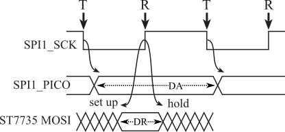
Figure 6.5.2. Data output and data input are synchronized to the clock.
Observation Synchronous protocols are fast and reliable.
: In Figure 6.5.2, the rising edge of the clock stores PICO into the peripheral. What is the definition of set up time?
: What is the definition of hold time?
: Define the data required interval in terms of the clocking edge, the set up time, and the hold time.
The SPI protocol sends 8 to 16 bits in a transmission. The interface to the ST7735R display utilizes an 8-bit frame, see Figure 6.5.3. The CS goes low, 8 bits are transmitted synchronized to 8 pulses on SCK, and then CS goes high.

Figure 6.5.3. One frame transmits 8 bits of data.
: What is the order of the bits sent serially with SPI?
The SPI protocol bidirectional transmission. We classify it as full duplex because data flows in both directions at the same time. The SPI interface supported two shift registers, one in the controller and a second in the peripheral. Both shift registers are clocked at the same time, using one edge to shift the data out and the other edge to shift the data in, see Figure 6.5.4.
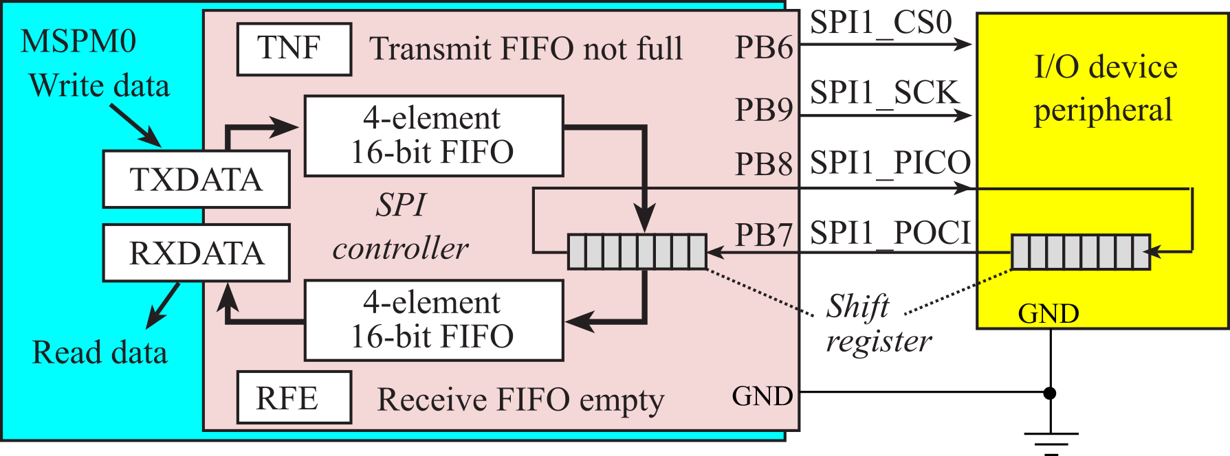
Figure 6.5.4. The SPI protocol exchanges the data in the two shift registers.
: Explain how SPI is full duplex?
In the following 8-Bit SPI Interactive, we are examining how an SPI bus would function. Additionally we want to examine how different factors such as the clock polarity(CPOL) and clock phase(CPHA) can affect how we are reading/interpretting the data produced.
: What makes this protocol both fast and reliable?
6.6. ST7735R Interfacing
In this section we will interface a ST7735R LCD using SPI protocol. The interface to the ST7735R will be classified as simplex because data will only flow from controller to peripheral. Figure 6.6.1 shows the interface to the Adafruit LCD. Connections for other ST7735R LCDs can be found in the starter code for this class.

Figure 6.6.1. MSPM0G3507 interfaced to the Adafruit ST7735R LCD.
Figure 6.6.2. shows the 128 by 160 pixel color display

Figure 6.6.2. ST7735R display with 160 by 128 16-bit color pixels.
Video 6.6.1. Interfacing the ST7735R LCD.
: How does the ST7735R software driver specify color?
Before we output data or commands to the display, we will check a status flag and wait for the previous operation to complete. Busy-wait synchronization is very simple and is appropriate for I/O devices that are fast and predicable. D/C stands for data/command; you will make D/C high to send data and low to send a command. Because the LCD is so fast we will use "busy-wait" synchronization, which means before the software issues an output command to the LCD, it will wait until the display is not busy. In particular, the software will wait for the previous LCD command to complete.
: What does the D/C pin do?
: What does the TFT_CS pin do?
: What does the MOSI pin do?
: What does the SCK pin do?
Video 6.6.2. Synchronizing software to hardware.
The following pseudo-code and Figure 6.6.3 shows the steps to interact with the LCD using the SPI module. The SPI module uses a first in first out (FIFO) queue built into the hardware. Bit 4 of the SPI1->STAT register is busy. If busy is 1, it means it cannot accept another command at this point. If busy is 0, it means it ready and can accept another command. Bit 1 of the SPI1->STAT register is TNF, which stands for transmitter FIFO not full. If TNF is 0, it means the transmitter FIFO is full and it cannot accept another data output at this point. If TNF is 1, it means the FIFO is not full and can accept another data output. Notice that this interface will wait before and after each command, however multiple data outputs can occur as long as there in room in the FIFO.
writecommand: Involves 6 steps performed to send 8-bit Commands to the
LCD
1. Read SPI1->STAT and check bit 4,
2. If bit 4 is high, loop back to step 1 (wait for BUSY
bit to be low)
3. Clear D/C=PA13 to zero (D/C pin configured for COMMAND)
4. Write the command to SPI1->TXDATA
5. Read SPI1->STAT and check bit 4,
6. If bit 4 is high loop back to step 5 (wait for BUSY bit
to be low)
writedata: Involves 4 steps performed to send 8-bit Data to the LCD:
1. Read SPI1->STAT and check bit 1,
2. If bit 1 is low, loop back to step 1 (wait for TNF bit
to be one)
3. Set D/C=PA13 to one (D/C pin configured for DATA)
4. Write the 8-bit data to SPI1->TXDATA
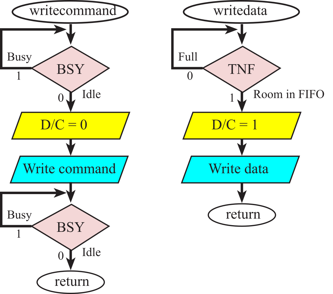
Figure 6.6.3. Busy-wait synchronization is used to send commands and data to the display.
: What does busy-wait mean?
At the lowest level each ASCII character is mapped to an image. This mapping is called a font. The following figure and program shows how the character '6' is created on the screen as a 5 by 8 pixel image (the actual pixels that vary for each character are 5 columns by 7 rows with the bottom row being all zeros). The driver automatically inserts one blank line (column) in between characters, so each character requires 6 by 8 pixels on the screen.
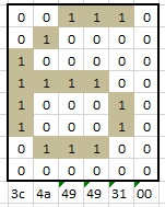
Figure 6.6.4. ST7735R character font is 5 wide by 8-tall pixels.
static const uint8_t Font[] = {
0x00, 0x00, 0x00, 0x00, 0x00, // 0x00
0x3E, 0x5B, 0x4F, 0x5B, 0x3E, // 0x01
...
0x3C, 0x4A, 0x49, 0x49, 0x31, // 0x36= '6'
...
0x00, 0x00, 0x00, 0x00, 0x00 // 0xFF
};
Program 6.6.1. ST7735R character font is 5 wide by 8-tall pixels.
There is one image for all 8 bit possibilities from 0 to 0xFF. To handle extended ASCII, which are the values 0x80 to 0xFF, make sure to change the compiler settings to select unsigned for the char type. Execute Project->Options, in the C/C++ tab deselect the box "Plain char is signed", making char unsigned.
: How many characters can fit across one row of the LCD screen?
: The ST7735R software driver uses 10 pixels in the vertical direction for each row of characters. How many rows of characters can fit on the LCD screen?
There is a rich set of graphics functions available for the ST7735R, allowing you to create amplitude versus time, or bit-mapped graphics. Refer to the ST7735R.h header file for more details.
6.7. Fixed-point Numbers
The value of a fixed point number is an integer times a constant.
The integer is stored in the computer and hence, can vary. The constant Δ is not stored, but it is known and fixed.
value = integer * Δ
The Δ (aka resolution) is a power of 10 or power of 2 depending on whether we are
representing a decimal- or binary fixed-point number. For example if Δ = 10-3 then the
smallest fraction we can represent is 0.001, hence the term resolution.
Video 6.7.1. Fixed-point numbers.
: When do we use decimal fixed point rather than binary fixed point?
: We wish to represent the sqrt(2)=1.4142135623730950488016887242097 as a decimal fixed number with a resolution of 0.001. What integer value do we use?
: We wish to represent 0.75 as a binary fixed number with a resolution of 2^-3 (1/8). What integer value do we use?
We will use fixed-point numbers when we wish to express values in our software that have noninteger values. In order to design a fixed-point system the range of values must be known. A fixed-point number contains two parts. The first part is a variable integer, called I. This variable integer may be signed or unsigned. An unsigned fixed-point number is one that has an unsigned variable integer. A signed fixed-point number is one that has a signed variable integer. The precision of a number system is the total number of distinguishable values that can be represented. The precision of a fixed-point number is determined by the number of bits used to store the variable integer. Therefore, to use a fixed-point system, the precision must be less than or equal to 32 bits or 232 alternatives. On the Cortex-M processor, we typically use 32 bits, but 8 or 16 bits could be used. The variable integer is saved in memory and is manipulated by software. These manipulations include but are not limited to load, store, shift, add, subtract, multiply, and divide. The second part of a fixed-point number is a fixed constant, called Δ. The fixed constant is defined at design time and cannot be changed at run time. The fixed constant defines the resolution of the number system. The fixed constant is not stored in memory. Usually we specify the value of this fixed constant using software comments to explain our fixed-point algorithm. The value of the fixed-point number is defined as the product of the variable integer times the fixed constant:
Fixed-point number = I * Δ
The resolution of a number is the smallest difference that can be represented. In the case of fixed-point numbers, the resolution is equal to the fixed constant, Δ. Sometimes we express the resolution of the number as its units. For example, a decimal fixed-point number with a resolution of 0.001 volts is really the same thing as an integer with units of mV. When inputting numbers from a keyboard or outputting numbers to a display, it is usually convenient to use decimal fixed point. With decimal fixed point the fixed constant is a power of 10.
Decimal fixed-point number = I * 10m for some constant integer m
Again, the constant m is fixed and is not stored in memory. Decimal fixed point will be easy to input or output to humans, while binary fixed point will be easier to use when performing mathematical calculations. With binary fixed point the fixed constant is a power of 2. There is a standard nomenclature for binary fixed point numbers called the Q-Format. The format Qm.n means there are m bits to the left of the binary point and n bits to the right of the binary point, resulting in m+n total bits stored in the computer. An alternate format is pQn, meaning there are p total bits and n bits to the right of the binary point.
Binary fixed-point number = I * 2n for some constant integer n
Common error: It is wrong to think the format Qm.n is stored on the computer as two integers: an m-bit integer and an n-bit integer. Rather, what is stored on the computer is one integer with m+n bits.
Observation: If the range of numbers is known and small, then the numbers can be represented in a fixed-point format.
In the first example, we will develop the equations that a microcontroller would need to implement a digital voltmeter. The MSPM0 family of microcontrollers has a built-in analog to digital converter (ADC) that can be used to transform an analog signal into digital form. The 12-bit ADC analog input range is 0 to +3.3 V, and the ADC digital output varies 0 to 4095 respectively. Let Vin be the analog voltage in volts and n be the digital ADC output, then the equation that relates the analog to digital conversion is
Vin = 3.3*n/4095 = 0.00080586 *n
Resolution is defined as the smallest change in voltage that the ADC can detect. This ADC has a resolution of about 0.8 mV. In other words, the analog voltage must increase or decrease by 0.8 mV for the digital output of the ADC to change by at least one bit. It would be inappropriate to save the voltage as an integer, because the only integers in this range are 0, 1, 2, and 3. Because floating point is not supported by the MSPM0 hardware using floating point will result in very slow execution speed. Therefore the voltage data will be saved in fixed-point format, because it will take less memory and execute faster. Decimal fixed point is chosen because the voltage data for this voltmeter will be displayed. A fixed-point resolution of Δ=0.001 V is chosen because it is about equal to the ADC resolution. Table 6.7.1 shows the performance of the system. The table shows us that we need to store the variable part of the fixed-point number in at least 16 bits.
|
Vin (V) Analog input |
n ADC digital output |
I (0.001 V) variable part of the fixed-point data |
|
0.000 |
0 |
0 |
|
0.001 |
1 |
1 |
|
1.000 |
1241 |
1000 |
|
1.650 |
2048 |
1650 |
|
3.300 |
4095 |
3300 |
Table 6.7.1. Performance data of a microcomputer-based voltmeter.
One possible software formula to convert n into I is as follows.
I = (3300*n + 2048)/4095, where I is defined as Vin = I*0.001V
It is very important to carefully consider the order of operations when performing multiple integer calculations. There are two mistakes that can happen. The first error is overflow, and it is easy to detect. Overflow occurs when the result of a calculation exceeds the range of the number system. The two solutions of the overflow problem were discussed earlier, promotion and ceiling/floor. The other error is called drop-out. Drop-out occurs after a right shift or a divide, and the consequence is that an intermediate result loses its ability to represent all of the values. To avoid drop-out, it is very important to divide last when performing multiple integer calculations. If you divided first, e.g., I=3300*(n/4095), then the values of I would be only 0, or 3300. The addition of "2048" has the effect of rounding to the closest integer. The value 2048 is selected because it is about one half of the denominator. For example, the calculation (3300*n)/4095=0 for n=1, whereas the "(3300*n+2048)/4096" calculation yields the better answer of 1. A display algorithm for this decimal fixed-point format is shown the next section.
When adding or subtracting two fixed-point numbers with the same Δ, we simply add or subtract their integer parts. First, let x, y, and z be three fixed-point numbers with the same Δ. Let x=I*Δ, y=J*Δ, and z=K*Δ. To perform z = x+y, we simply calculate K = I+J. Similarly, to subtract z = x-y, we simply calculate K=I-J. When adding or subtracting fixed-point numbers with different fixed parts, we must first convert the two inputs to the format of the result before adding or subtracting. This is where binary fixed point is more convenient, because the conversion process involves shifting rather than multiplication/division.
In this next example, let x, y, and z be three binary fixed-point numbers with different resolutions. In particular, we define x to be I*2-5, y to be J*2-2, and z to be K*2-3. To convert x to the format of z, we divide I by 4 (right shift twice). To convert y to the format of z, we multiply J by 2 (left shift once). To perform z = x+y, we calculate
K = (I>>2)+(J<<1)
For the general case, we define x to be I*2n, y to be J*2m, and z to be K*2p. To perform any general operation, we derive the fixed-point calculation by starting with desired result. For addition, we have z = x+y. Next, we substitute the definitions of each fixed-point parameter
K*2p = I*2n + J*2m
Lastly, we solve for the integer part of the result
K = I*2n-p + J*2m-p
For multiplication, we have z=x*y. Again, we substitute the definitions of each fixed-point parameter
K*2p = I*2n * J*2m
Lastly, we solve for the integer part of the result
K = I*J*2n+m-p
For division, we have z=x/y. Again, we substitute the definitions of each fixed-point parameter
K*2p = I*2n / J*2m
Lastly, we solve for the integer part of the result
K = I/J*2n-m-p
Again, it is very important to carefully consider the order of operations when performing multiple integer calculations. We must worry about overflow and drop out. In particular, in the division example, if (n-m-p) is positive then the left shift (I*2n-m-p) should be performed before the divide (/J). We can use these fixed-point algorithms to perform complex operations using the integer functions on our microcontroller.
As an example, we can rewrite the following digital filter using fixed-point calculations.
y = x -0.0532672*x1 + x2 + 0.0506038*y1-0.9025*y2
In this case, the variables y, y1, y2, x, x1, and x2 are all integers, but the constants will be expressed in binary fixed-point format. The value -0.0532672 can be approximated by ‑14*2-8. The value 0.0506038 can be approximated by 13*2-8. Lastly, the value -0.9025 can be approximated by -231*2-8. The fixed-point implementation of this digital filter is
y = x + x2 + (-14*x1+13*y1-231*y2)>>8
Common Error: Lazy or incompetent programmers use floating point in many situations where fixed-point would be preferable.
Observation: As the fixed constant is made smaller, the resolution of the fixed-point representation is improved, but the variable integer part also increases. Unfortunately, larger integers will require more bits for storage and calculations.
: Using a fixed constant of 2-8, rewrite the digital equation F= 1.8*C+32 in binary fixed-point format.
: Using a fixed constant of 10-3, rewrite the digital filter y = x‑0.0532672*x1+x2+0.0506038*y1-0.9025*y2 in decimal fixed-point format.
: Assume resistors R1, R2, R3 are the integer parts of 16-bit unsigned binary fixed-point numbers with a fixed constant of 2-4. Write an equation to calculate R3 = R1||R2 (parallel combination.)
The purpose of this example is to study overflow and drop-out errors during integer calculations. The objective of the software is to calculate the circumference of a circle given its radius.
c = 2 π r
Assume r is an unsigned 32-bit fixed-point number with a resolution of 0.001 cm. c is also fixed-point with the same resolution. I.e., c = C*0.001 cm and r = R*0.001 cm, where C and R are unsigned 32-bit variable integers. Given 32-bit variables, the values of c can range from 0.000 to 4,294,967.295 cm. If we divide this by 2π, this calculation should work for values of r ranging from 0 to 683,565.275 cm. We substitute the definitions of c and r into the equation to get an exact relationship between input R and output C,
C = 2*π*R
We need to convert this equation to a function with integer operations. One simple possibility is
C = 6283*R/1000
The difficulty with this equation is the multiply 6283 is the possibility of overflow. The largest value r can be without overflow is 232/6283*0.001cm = 683cm, which is a 1000 times smaller than the range predicted by the c = 2 π r equation. There are two approaches to reducing the effect of overflow. The first approach would be to promote to 64 bits, perform the operation, and then demote back to 32 bits. The second approach is the find a better approximation for 2π. If we search the space of all integers (I1, I2) less than 255, such that I1/I2 is as close to 2π as possible, we find this possibility
C = 245*R/39
Notice that 2π-245/39 = 2π-6.28205 = 0.0011, which means this calculation is just as accurate as the 6283/1000 approximation. However, the multiply by 245 is less likely to cause an overflow error as compared to the multiply by 6283. When dividing by an unsigned number we can implement rounding by adding half of the divisor to the dividend. In this example, we add 20.
C = (245*R+20)/39
Observation: The MSPM0G3507 has a hardware accelerator capable of multiply, divide, sine, cosine, arctan, and square root. These operations use binary fixed-point formats. See the MATHACL chapter in the Technical Reference Manual.
6.8. IEEE Floating-point numbers
If the range of numbers is unknown or large, then the numbers must be represented in a floating-point format. Conversely, we can use fixed point when the range of values is small and known. Therefore, we will not need floating-point operations for most embedded system applications because fixed point is sufficient. Furthermore, if the processor does not have floating-point instructions then a floating-point implementation will run much slower than the corresponding fixed-point implementation. However, it is appropriate to know the definition of floating point. NASA believes that there are on the order of 1021 stars in our Universe. Manipulating large numbers like these is not possible using integer or fixed-point formats. Another limitation with integer or fixed-point numbers is there are some situations where the range of values is not known at the time the software is being designed. In a Physics research project, you might be asked to count the rate at which particles strike a sensor. Since the experiment has never been performed before, you do not know in advance whether there will be 1 per second or 1 trillion per second. The applications with numbers of large or unknown range can be solved with floating-point numbers. Floating point is similar in format to fixed point, except the exponent is allowed to change at run time. Consequently, both the exponent and the mantissa will be stored. Just like with fixed-point numbers we will use binary exponents for internal calculations, and decimal exponents when interfacing with humans. This number system is called floating point because as the exponent varies, the binary point or decimal point moves.
The IEEE Standard for Binary Floating-Point Arithmetic or ANSI/IEEE Std 754-1985 is the most widely-used format for floating-point numbers. There are three common IEEE formats: single-precision (32-bit), double-precision (64-bit), and double-extended precision (80-bits). The 32-bit short real format as implemented is presented here. The floating-point format, f, for the single-precision data type is shown in Figure 6.8.1. Computers use binary floating point because it is faster to shift than it is to multiply/divide by 10.
Bit 31 Mantissa sign, s=0 for positive, s=1 for negative
Bits 30:23 8-bit biased binary exponent 0 ≤ e ≤ 255
Bits 22:0 24-bit mantissa, m, expressed as a binary fraction,
A binary 1 as the most significant bit is implied.
m = 1.m1m2m3...m23

Figure 6.8.1. 32-bit single-precision floating-point format.
The value of a single-precision floating-point number is
f = (-1)s * 2e-127* m
The range of values that can be represented in the single-precision format is about ±10-38 to ±10+38. The 24-bit mantissa yields a precision of about 7 decimal digits. The floating-point value is zero if both e and m are zero. Because of the sign bit, there are two zeros, positive and negative, which behave the same during calculations. To illustrate floating point, we will calculate the single-precision representation of the number 10. To find the binary representation of a floating-point number, first extract the sign.
10 = (-1)0 *10
Step 2, multiply or divide by two until the mantissa is greater than or equal to 1, but less than 2.
10 = (-1)0 *23* 1.25
Step 3, the exponent e is equal to the number of divide by twos plus 127.
10 = (-1)0 *2130-127* 1.25
Step 4, separate the 1 from the mantissa. Recall that the 1 will not be stored.
10 = (-1)0 *2130-127* (1+0.25)
Step 5, express the mantissa as a binary fixed-point number with a fixed constant of 2-23.
10 = (-1)0 *2130-127* (1+2097152*2-23)
Step 6, convert the exponent and mantissa components to hexadecimal.
10 = (-1)0 *20x82-127* (1+0x200000*2-23)
Step 7, extract s, e, m terms, convert hexadecimal to binary
10 = (0,0x82,0x200000) = (0,10000010,01000000000000000000000)
Sometimes this conversion does not yield an exact representation, as in the case of 0.1. In particular, the fixed-point representation of 0.6 is only an approximation.
Step 1 0.1 = (-1)0 *0.1
Step 2 0.1 = (-1)0 *2-4* 1.6
Step 3 0.1 = (-1)0 *2123-127 * 1.6
Step 4 0.1 = (-1)0 *2123-127 * (1+0.6)
Step 5 0.1 ≈ (-1)0 *2123-127* (1+5033165*2-23)
Step 6 0.1 ≈ (-1)0 *20x7B-127* (1+0x4CCCCD*2-23)
Step 7 0.1 ≈ (0,0x7B,0x4CCCCD) = (0,01111011,10011001100110011001101)
The following example shows the steps in finding the floating-point approximation for π.
Step 1 π = (-1)0 *π
Step 2 π ≈ (-1)0 *21* 1.570796327
Step 3 π ≈ (-1)0 *2128-127* 1.570796327
Step 4 π ≈ (-1)0 *2128-127* (1+0.570796327)
Step 5 π ≈ (-1)0 *2128-127* (1+4788187*2-23)
Step 6 π ≈ (-1)0 *20x80-127* (1+0x490FDB*2-23)
Step 7 π ≈ (0,0x80,0x490FDB) = (0,10000000,10010010000111111011011)
There are some special cases for floating-point numbers. When e is 255, the number is considered as plus or minus infinity, which probably resulted from an overflow during calculation. When e is 0, the number is considered as denormalized. The value of the mantissa of a denormalized number is less than 1. A denormalized short result number has the value,
f = (-1)s * 2-126* m where m = 0.m1m2m3...m23
Observation: The floating-point zero is stored in denormalized format.
When two floating-point numbers are added or subtracted, the smaller one is first unnormalized. The mantissa of the smaller number is shifted right and its exponent is incremented until the two numbers have the same exponent. Then, the mantissas are added or subtracted. Lastly, the result is normalized. To illustrate the floating-point addition, consider the case of 10+0.1. First, we show the original numbers in floating-point format. The mantissa is shown in binary format.
10.0 = (-1)0 *23 * 1.01000000000000000000000
+ 0.1 = (-1)0 *2-4* 1.10011001100110011001101
Every time the exponent is incremented the mantissa is shifted to the right. Notice that 7 binary digits are lost. The 0.1 number is unnormalized, but now the two numbers have the same exponent. Often the result of the addition or subtraction will need to be normalized. In this case the sum did not need normalization.
10.0 = (-1)0 *23 * 1.01000000000000000000000
+ 0.1 = (-1)0 *23 * 0.00000011001100110011001 1001101
10.1 = (-1)0 *23 * 1.01000011001100110011001
When two floating-point numbers are multiplied, their mantissas are multiplied and their exponents are added. When dividing two floating-point numbers, their mantissas are divided and their exponents are subtracted. After multiplication and division, the result is normalized. To illustrate the floating-point multiplication, consider the case of 10*0.1. Let m1, m2 be the values of the two mantissas. Since the range is 1 ≤ m1, m2 < 2, the product m1*m2 will vary from 1 ≤ m1*m2 < 4.
10.0 = (-1)0 *23 * 1.01000000000000000000000
* 0.1 = (-1)0 *2-4 * 1.10011001100110011001101
1.0 = (-1)0 *2-1 *10.00000000000000000000000
The result needs to be normalized.
1.0 = (-1)0 *20 * 1.00000000000000000000000
Roundoff is the error that occurs as a result of an arithmetic operation. For example, the multiplication of two 64-bit mantissas yields a 128-bit product. The final result is normalized into a normalized floating-point number with a 64-bit mantissa. Roundoff is the error caused by discarding the least significant bits of the product. Roundoff during addition and subtraction can occur in two places. First, an error can result when the smaller number is shifted right. Second, when two n-bit numbers are added the result is n+1 bits, so an error can occur as the n+1 sum is squeezed back into an n-bit result.
Truncation is the error that occurs when a number is converted from one format to another. For example, when an 80-bit floating-point number is converted to 32-bit floating-point format, 40 bits are lost as the 64-bit mantissa is truncated to fit into the 24-bit mantissa. Recall, the number 0.1 could not be exactly represented as a short real floating-point number. This is an example of truncation as the true fraction was truncated to fit into the finite number of bits available.
We conclude this section by comparing floating point and fixed point. Let's summarize the definitions of:
Resolution is the smallest difference in values that can be represented.
Range is the smallest value to the largest value that can be represented.
Precision is the number of different values that can be represented in bits or alternatives.
Accuracy is defined as the difference between truth and the
value approximated by the number system.
If the range is known and small and a fixed-point system can be used, then a 32-bit fixed-point number system will have better resolution than a 32-bit floating-point system. For a fixed range of values (i.e., one with a constant exponent), a 32-bit floating-point system has only 23 bits of precision, while a 32-bit fixed-point system has 9 more bits of precision.
Consider the situation where we wish to represent distance in cm. The limitations of the ADC and transducer noise will set the measurement resolution. For example, assume the measurement resolution is 0.001cm. If we were to use a fixed-point number system, we could choose Δ = 0.001cm. Every measurement system also has a measurement range. Assume the range is 0 to 2cm. The integer part of the fixed-point number system would be 0 to 2000, and thus we could choose a 16-bit unsigned integer format. Conversely, we could use a floating-point number to represent distance. Table 6.8.1 compares the 16-bit Δ = 0.001cm fixed-point number system with the single-precision floating point number system. Both formats will be able to represent accurately all distances from 0 to 2cm. We define ConvertTime as the time it takes to convert a 12-bit ADC value into distance. We define OutTime as the time it takes to display the distance on the LCD screen.
|
Parameter |
Fixed point |
Floating point |
|
Size |
2 bytes |
4 bytes |
|
Range |
0 to 65.535 cm |
±10-38 to ±10+38 cm |
|
ConvertTime |
0.472us |
9.2us |
|
OutTime |
9.8ms |
15.7ms |
Table 6.8.1. Performance data of a microcomputer-based voltmeter.
For this example, since the measurement system is limited by the ADC and transducer noise to be 0.001cm, both fixed and floating point are equally accurate.
Consider second example, where the distance can vary from 0 to 2 cm, and we which to choose a number system with the best resolution and precision. Precision is defined as the number of difference numbers that can be represented in the system. A fixed-point number with an unsigned 32-bit integer and a Δ = 2-31 cm. The resolution is 2-31 cm and the precision is 32 bits. If we were to use a single precision floating point number, the resolution is only 2-23 cm and the precision is only 24 bits, because the exponent will be fixed for the 0 to 2cm range. I.e., there are only 223 floating point numbers between 0 and 1 cm, and there are only 223 floating point numbers between 1 and 2 cm.
Observation: When the range is small and known, a fixed-point system will be more accurate, more precise, have a better resolution, and execute faster than a floating-point system.
6.9. Numerical Output
Video 6.9.1. Converting integers to ASCII characters.
The Cortex M0 has a multiply instruction, MULS, but no divide. To implement numerical output of integers in decimal format, we will need division and modulus. The function in Program 6.9.1 takes two inputs and returns two outputs. It does not comply with AAPCS because it returns two values, in R0 and R1. However, we can call this function from other assembly routines.
Refer back to Section 1.7.7 for more examples of assembly functions that multiply and divide.
// Inputs: R0 is 32-bit dividend
// R1 is 16-bit divisor
// quotient*divisor + remainder = dividend
// Output: R0 is 16-bit quotient, assuming it fits
// R1 is 16-bit remainder (modulus)
udiv32_16:
PUSH {R4,LR}
LDR R4,=0x00010000 // bit mask
MOVS R3,#0 // quotient
MOVS R2,#16 // loop counter
LSLS R1,#15 // move divisor under dividend
udiv32_16_loop:
LSRS R4,R4,#1 // bit mask 15 to 0
CMP R0,R1 // need to subtract?
BLO udiv32_16_next
SUBS R0,R0,R1 // subtract divisor
ORRS R3,R3,R4 // set bit
udiv32_16_next:
LSRS R1,R1,#1
SUBS R2,R2,#1
BNE udiv32_16_loop
MOVS R1,R0 // remainder
MOVS R0,R3 // quotient
POP {R4,PC}
Program 6.9.1. 32-bit by 16-bit unsigned divide. It does not check for overflow.
For the following two checkpoints, assume R0 initially contains an unsigned integer of value n, and R1 is initially 10.
: What is the value of R0 after calling the udiv32_16 function?
: What is the value of R1 after calling the udiv32_16 function?
: Assume each instruction in udiv32_16 takes 2 bus cycles. Assume the BLO instruction never branches. Estimate execution speed of this function. Compare this speed to the 2 bus cycle time it takes to execute MULS.
: Give a mathematical equation relating the dividend, divisor, quotient, and remainder.
: Under what assumptions does this equation give a unique answer.
Video 6.9.2. Device Drivers, Successive Refinement, Number Conversions **bug at 12:38, should loop on CNT>0 and quit when CNT equals 0.**
Program 6.9.2 shows two implementations of factorial. The one on the top uses iteration, and the one on the bottom uses recursion. It is usually the case that a recursive algorithm can be rewritten in iterative form. Nevertheless, sometimes it is more convenient to implement the algorithm in recursive form.
|
// iterative implementation (22 bytes) |
// iterative implementation |
Program 6.9.2. Iterative and recursive solutions to factorial.
6.10. printf
A very powerful approach to I/O is to provide a high-level abstraction in such a way that the I/O device itself is hidden from the user. There are two printf projects on the book's web site. The overall purpose of each of these examples is to provide an output stream using the standard printf function. Using the project UART_busywait, we send the output data stream through UART to the PC. The project ST7735 implements a similar approach sending data through SPI to a color LCD ST7735 display. In each implementation, there is an initialization function that must be called once, and a general function printf() we use to output data in a standard way.
At the low level, we implement how the output actually happens by writing a uart_write function. The uart_write function is a private and implemented inside the UART.c,
At the high level, the user performs output by calling printf. This abstraction clearly separates what it does (printf outputs information) from how it works (sends data to the display over UART or SPI). By rewriting the low level, we could redirect the output to other devices.
The call to printf has a string parameter followed by a list of values to display. Assume cc is an 8-bit variable containing 0x56 ('V'), xx is a 32-bit variable containing 100, and yy is a 16-bit variable containing -100, zz is a 32-bit floating containing 3.14159265. The following illustrate the use of printf. After the format parameter, printf requires at least as many additional arguments as specified in the format.
Example code Output
printf("Hello world\n"); Hello world
printf("cc = %c %d %#x\n",cc,cc,cc); cc = V 86 0x56
printf("xx = %c %d %#x\n",xx,xx,xx); xx = d 100 0x64
printf("yy = %d %#x\n",yy,yy); yy = -100 0xffffff9c
printf("zz = %f %3.2f\n",zz,zz); zz = 3.141593 3.14
Escape sequences are used to display non-printing and hard-to-print characters. In general, these characters control how text is positioned on the screen, see Table 6.10.1.
|
Character |
Value |
Escape Sequence |
|
backslash |
0x5C |
\\ |
|
carriage return |
0x0D |
\r |
|
double quote |
0x22 |
\" |
|
horizontal tab |
0x08 |
\t |
|
newline |
0x0A |
\n |
|
null character |
0x00 |
\0 |
|
single quote |
0x27 |
\' |
|
STX |
0x02 |
\x02 (this syntax works for any 2-digit hex value) |
|
question mark |
0x3F |
\? |
Table 6.10.1. Escape sequences.
When the program is executed, the control string will be displayed exactly as it appears in the program with two exceptions. First, the computer will replace each conversion specification with a value given in the other arguments part of the printf statement. Second, escape sequences will be replaced with special non-printing and hard-to-print characters. To display the contents of a variable we add a % tag into the format string the specifier defines the type as listed in Table 6.10.2. The floating-point specifiers have been omitted.
%[flags][width][.precision]specifier
|
Specifier |
Output |
Example |
|
c |
Character |
a |
|
d or i |
Signed decimal integer |
392 |
|
ld |
Signed 32-bit long decimal integer |
1234567890 |
|
e |
Scientific notation |
6.022141e23 |
|
E |
Scientific notation, capital letter |
6.022141E23 |
|
f |
Floating point |
3.14159 |
|
o |
Unsigned octal |
610 |
|
s |
String of characters |
sample |
|
u |
Unsigned decimal integer |
7235 |
|
x |
Unsigned hexadecimal integer |
7fa |
|
X |
Unsigned hexadecimal integer (capital letters) |
7FA |
|
% |
%% will write % to stdout |
% |
Table 6.10.2. Format specifiers.
The tag can also contain flags, width, .precision, and length sub-specifiers. The flags are listed in Table 6.10.3. If the width is present, it specifies the minimum number of characters to be printed. If the value to be printed is shorter than this number, the result is padded with blank spaces. The value is not truncated even if the result is larger. The .precision sub-specifier specifies the minimum number of digits to be written (d, i, o, u, x, X). If the value to be written is shorter than this number, the result is padded with leading zeros. The value is not truncated if the result requires more digits. A precision of 0 means that no character is written for the value 0. For s the .precision is the maximum number of characters to be printed. For c type is .precision has no effect. For floating point .precision is the number of digits after the decimal.
|
Flags |
Description |
|
- |
Left-justify within the given field width |
|
+ |
Forces the result to have a plus or minus sign |
|
(space) |
If no sign is going to be written, a blank space is inserted before the value. |
|
# |
Used with o, x or X specifiers the value is preceded with 0, 0x or 0X respectively for values different than zero. |
|
0 |
Left-pads the number with zeroes (0) instead of spaces, where padding is specified (see width sub-specifier). |
Table 6.10.3. Flag sub-specifiers.
If successful, printf will return the total number of characters written. On failure, a negative number is returned. The start of a format specifier is signified by a percent sign and the end is signified by one of the letter codes in Table 6.10.3. Each format specifier will be replaced by a value from the argument list converted to the specified format. These optional fields typical occur in this order. The pound sign ('#') specifies that the value should be converted to an alternate form. The alternate form for hexadecimal adds the 0x or 0X. The alternate form for octal is a leading zero.
printf("%x", 11); // prints 'b'
printf("%#x", 11); // prints '0xb'
printf("%X", 11); // prints 'B'
printf("%#X", 11); // prints '0XB'
printf("%o", 11); // prints '13'
printf("%#o", 11); // prints '013'
The zero ('0') specifies zero-padding. The converted value is padded on the left with the specified number of zeros minus the number of digits to be printed. This is described in more detail below.
printf("%d", 9); // prints '9'
printf("%4d", 9); // prints ' 9'
printf("%04d", 9); // prints '0009'
printf("%04d", 123); // prints '0123'
A minus sign ('-') specifies left justification. Without the minus, the format is right justified.
printf("%5d", 12); // prints ' 12' (right justified)
printf("%-5d", 12); // prints '12 ' (left justified)
A space (' ') specifies that a blank should be left before a positive number.
printf("% d", 9); // prints ' 9'
printf("% d", -9); // prints '-9'
The plus sign ('+') specifies that a sign always be placed before the value. The plus sign overrides a space if both are used.
printf("%+d", 9); // prints '+9'
printf("%+d", -9); // prints '-9'
A decimal digit specifies the minimum field width. Using the minus sign makes the format is left justified, otherwise it is right justified. Used with the zero-modifier for numeric conversions, the value is right-padded with zeros to fill the field width.
printf("%3d", 12); // prints ' 12' (right justified)
printf("%-3d", 12); // prints '12 ' (left justified) printf("%3d", 123); // prints '123' (filled up)
printf("%3d", 1234); // prints '1234' (bigger than 3 width)
A precision value in the form of a period ('.'), followed by an optional digit string. If the digit string is omitted, a precision of zero is used. When used with decimal, hexadecimal or octal integers, it specifies the minimum number of digits to print. For floating point output, it specifies the number of digits after the decimal place. For the 's' (string) conversion, it specifies the maximum number of characters of the string to print, which is quite useful to make sure long strings don't exceed their field width.
printf("%.3d", 7); // prints '007'
printf("%.3d", 12345); // prints '12345'
printf("%3s", "Jonathan"); // prints 'Jonathan'
printf("%.3s", "Jonathan"); // prints 'Jon'
printf("%3s", "JV"); // prints 'JV '
printf("%.3s", "JV"); // prints 'JV'
Consider a decimal fixed-point number with units 0.001 cm. For example, if the value of distance is equal to 1234, this means the distance is 1.234 cm. Assume the distance varies from 0 to 99.999 cm. This C code could be used to print the value of the number in such a way that exactly 20 characters are printed for all values of distance from 0 to 99999. The first format specifier (%2u) prints the integer part in exactly two characters, and the second format specifier (%.3u) prints the fractional part in exactly three characters.
printf("Distance = %2u.%.3u cm", distance/1000,distance%1000);
Value Output
0 Distance = 0.000 cm
1 Distance = 0.001 cm
99 Distance = 0.099 cm
123 Distance = 0.123 cm
1234 Distance = 1.234 cm
12345 Distance = 12.345 cm
6.11. Lab 6. LCD Device Driver for the Sitronix ST7735
The details of the lab 6 can be found in GoogleDocs:
Lab 6. LCD Device Driver for the Sitronix ST7735
This material was created to teach ECE319K at the University of Texas at Austin
Reprinted with approval from Introduction to Embedded Systems Using the MSPM0+, ISBN: 979-8852536594

Embedded
Systems - Shape the World by Jonathan Valvano and Ramesh Yerraballi is
licensed under a Creative
Commons
Attribution-NonCommercial-NoDerivatives 4.0 International License.
Based on a work at http://users.ece.utexas.edu/~valvano/mspm0/