Cortex M0+ Assembly Reference
My purpose in writing this book is not to provide a complete description of the ARM Cortex M0+ or any particular microcontroller. Rather the book is a learning tool for college students majoring in engineering and science. As such, this appendix is not a complete list of all Thumb instructions. It gives details on 36 instructions introduced in this book. On the other hand, these are complete reference manuals for the Cortex-M0+ processor and MSPM0+ microcontroller.
Arm_Architecture_v6m_Reference_Manual.pdf
MSPM0+ Assembly Instruction Set
ArmClang_Reference_Guide_100067_0612_00_en.pdf
Arm Clang Reference Guide
Cortex_M0p_TRM.pdf
Cortex M0+ Technical Reference Guide
LP_MSPM0G3507_users_guide.pdf
MSPM0G3507 LaunchPad Users Guide.pdf Guide
mspm0g3507.pdf
Data sheet of MSPM0G3507 microcontroller
MSPM0G-TRM.pdf
MSPM0G Technical Reference Guide (explains I/O Ports)
Memory access and register move instructions
LDR Rt, [Rn] // 32-bit load, EA=Rn
LDR Rt, [Rn,#n5] // 32-bit load, EA=Rn+n5
LDR Rt, [SP,#n8] // 32-bit load, EA=SP+n8
LDR Rt, [Rn,Rm] // 32-bit load, EA=Rn+Rm
LDR Rt, label2 // read contents at label2, PC rel, EA=PC+relative
LDR Rt, =number // Rt=number, PC relative, EA=PC+relative
LDRH Rt, [Rn] // 16-bit unsigned load, EA=Rn
LDRH Rt, [Rn,#h5] // 16-bit unsigned load, EA=Rn+h5
LDRH Rt, [Rn,Rm] // 16-bit unsigned load, EA=Rn+Rm
LDRSH Rt, [Rn,Rm] // 16-bit signed load, EA=Rn+Rm
LDRB Rt, [Rn] // 8-bit unsigned load, EA=Rn
LDRB Rt, [Rn,#imm5] // 8-bit unsigned load, EA=Rn+imm5
LDRB Rt, [Rn,Rm] // 8-bit unsigned load, EA=Rn+Rm
LDRSB Rt, [Rn,Rm] // 8-bit signed load, EA=Rn+Rm
STR Rt, [Rn] // 32-bit store, EA=Rn
STR Rt, [Rn,#n5] // 32-bit store, EA=Rn+n5
STR Rt, [SP,#n8] // 32-bit store, EA=SP+n8
STR Rt, [Rn,Rm] // 32-bit store, EA=Rn+Rm
STRH Rt, [Rn] // 16-bit store, EA=Rn
STRH Rt, [Rn,#h5] // 16-bit store, EA=Rn+h5
STRH Rt, [Rn,Rm] // 16-bit store, EA=Rn+Rm
STRB Rt, [Rn] // 8-bit store, EA=Rn
STRB Rt, [Rn,#imm5] // 8-bit store, EA=Rn+imm5
STRB Rt, [Rn,Rm] // 8-bit store, EA=Rn+Rm
MOV Rd2, Rm2 // move contents of Rm2 into Rd2
MOVS Rd, Rm // move contents of Rm into Rd, set flags
MOVS Rd, #imm8 // move contents of imm8 into Rd, set flags
MVNS Rd, Rm // set Rd equal to ~Rm (logical NOT)
Compare and Branch instructions
CMP Rd, #imm8 // Rd – imm8, set flags
CMP Rn, Rm // Rn – Rm, set flags
CMN Rn, Rm // Rn - (-Rm), set flags
B label0 // branch to label0 Always
BEQ label // branch if Z == 1 Equal
BNE label // branch if Z == 0 Not equal
BCS/BHS label // branch if C == 1 Higher or same, unsigned ≥
BCC/BLO label // branch if C == 0 Lower, unsigned <
BMI label // branch if N == 1 Negative
BPL label // branch if N == 0 Positive or zero
BVS label // branch if V == 1 Overflow
BVC label // branch if V == 0 No overflow
BHI label // branch if C==1 and Z==0 Higher, unsigned >
BLS label // branch if C==0 or Z==1 Lower or same, unsigned ≤
BGE label // branch if N == V Greater than or equal, signed ≥
BLT label // branch if N != V Less than, signed <
BGT label // branch if Z==0 and N==V Greater than, signed >
BLE label // branch if Z==1 or N!=V Less than or equal, signed ≤
Function call, function return, stack, and interrupt instructions
PUSH {reglist} // push 32-bit registers onto stack, R0-R7,LR
POP {reglist} // pop 32-bit from stack into registers, R0-R7,PC
ADD Rd, SP, #n8 // Rd = SP+n8
ADD SP, SP, #n7 // SP = SP+n7
SUB SP, SP, #imm7w // SP = SP-imm7w
BL label1 // branch to subroutine at label1, anywhere
BLX Rm4 // branch to subroutine specified by Rm4, R0-R12
BX Rm3 // branch to location specified by Rm3, R0-R12,LR
CPSIE I // enable interrupts (I=0)
CPSID I // disable interrupts (I=1)
WFI // sleep and wait for interrupt
SVC #imm8 // software interrupt
Logical and shift instructions
ANDS Rdn, Rm // Rdn = Rdn&Rm
ORRS Rdn, Rm // Rdn = Rdn|Rm
EORS Rdn, Rm // Rdn = Rdn^Rm
BICS Rdn, Rm // Rdn = Rdn&(~Rm)
LSRS Rd, Rd, Rs // logical shift right Rd=Rd>>Rs (unsigned)
LSRS Rd, Rm, #n // logical shift right Rd=Rm>>n (unsigned), 0 to 31
ASRS Rd, Rm, Rs // arithmetic shift right Rd=Rd>>Rs (signed)
ASRS Rd, Rm, #n // arithmetic shift right Rd=Rm>>n (signed), 1 to 32
LSLS Rd, Rd, Rs // shift left Rd=Rd<<Rs (signed or unsigned)
LSLS Rd, Rm, #n // shift left Rd=Rm<<n (signed or unsigned), 1 to 32
Arithmetic instructions
ADDS Rd, Rn, #imm3 // Rd = Rn+imm3, set flags
ADDS Rdn, #imm8 // Rdn = Rdn+imm8, set flags
ADDS Rd, Rn, Rm // Rd = Rm+Rn, set flags
ADD Rd2, Rm // Rd2 = Rd2+Rm
SUBS Rd, Rn, #imm3 // Rd = Rn-imm3, set flags
SUBS Rdn, #imm8 // Rdn = Rdn-imm8, set flags
SUBS Rd, Rn, Rm // Rd = Rn-Rm
RSBS Rd, Rn, #0 // Rd = 0-Rn, set flags
MULS Rdn, Rdn, Rm // Multiply Rdn = Rdn*Rm, set flags
Notes
Rd Rdn Rm Rn Rt represent 32-bit registers R0 to R7
Rd2 Rm2 represent 32-bit registers R0 to R15
number any 32-bit value: signed, unsigned, or address
label0 -2048 to 2046, in multiples of 2, from PC
label -256 to 254, in multiples of 2, from PC
label2 any address within 0 to 1020, in multiples of 4, from PC
#h5 any value from 0 to 62 in multiples of 2
#n5 any value from 0 to 124 in multiples of 4
#n7 any value from 0 to 508 in multiples of 4
#n8 any value from 0 to 1020 in multiples of 4
#imm3 any value from 0 to 7
#imm5 any value from 0 to 31
#imm8 any value from 0 to 255
ADD
32-bit Addition
Syntax
ADDS Rd, Rn, #imm3 // Rd = Rn+imm3
ADDS Rdn, #imm8 // Rdn = Rdn+imm8
ADDS Rd, Rn, Rm // Rd = Rm+Rn
ADD Rd2, Rm // Rd2 = Rd2+Rm
ADD Rd, SP, #imm8w // Rd = SP+imm8w
ADD SP, SP, #imm7w // SP = SP+imm7w
Machine code (for instructions using PC or SP, see instruction manual)
|
15-9 |
8-6 |
5-3 |
2-0 |
|
|
0001110 |
imm3 |
Rn |
Rd |
ADDS Rd,Rn,#imm3 |
|
15-11 |
10-8 |
7-0 |
|
|
|
00110 |
Rdn |
imm8 |
ADDS Rdn,#imm8 |
|
|
15-9 |
8-6 |
5-3 |
2-0 |
|
|
0001100 |
Rm |
Rn |
Rd |
ADDS Rd,Rn,Rm |
|
15-7 |
6-3 |
2-0 |
|
|
|
010001000 |
Rd2 |
Rm |
ADD Rd2,Rm |
|
Operation
The ADD instruction adds two 32-bit values and stores the sum into the register closest to the op code. imm3 is a constant from 0 to 7. imm8 is a constant from 0 to 255. Values added to the SP must be powers of 4 (SP must be word aligned). So, imm7w is a constant from 0 to 508, and imm8w is a constant from 0 to 1020.
Restrictions
- Rd, Rdn, Rm, and Rn must be R0 to R7.
Condition Flags
If S is specified, these instructions update the N, Z, C and V flags according to the result. R=X+M, where X is initial register value, M is the second operand, and R is the final register value.
N: result is negative N = R31
Z:
result is zero ![]()
V: signed overflow ![]()
C:
unsigned overflow ![]()
Examples
ADD R11, R3 //R11=R11+R3
ADDS R4, R4, #100 //R4=R4+100, set flags
AND
32-bit Logical AND
 Syntax
ANDS Rdn, Rm // Rdn = Rdn&Rm
ANDS Rdn, Rdn, Rm // Rdn = Rdn&Rm
Machine code
|
15-6 |
5-3 |
2-0 |
|
|
|
0100000000 |
Rm |
Rdn |
|
|
Operation
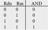
The AND instruction performs a 32-bit bitwise AND operation on the values in Rdn and Rm and places the result into Rdn. The AND instruction is useful for selecting bits. You specify which bits to select in the Rm.
Rd = Rn & Rm
Restrictions
- Rdn and Rm must be R0 to R7.
Condition Flags
The ANDS instruction updates the N and Z flags according to the result, Rdn. It does not affect the C or V flags.
N: result is negative N = R31
Z:
result is zero ![]()
Examples
ANDS R1, R7 //R1=R1&R7
ANDS R0, R0, R5 //R0=R0&R5
ASR
32-bit Arithmetic Shift Right
Syntax
ASRS Rd, Rm, #n
ASRS Rdn, Rm
ASRS Rdn, Rdn, Rm
where n is the shift length (1 to 32).
Machine code
|
15-11 |
10-6 |
5-3 |
2-0 |
|
|
00010 |
imm5 |
Rm |
Rd |
ASRS Rd,Rm,#n |
|
15-6 |
5-3 |
2-0 |
|
|
|
0100000100 |
Rm |
Rdn |
ASRS Rdn,Rm |
|
Operation
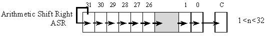
ASR moves the bits in the register Rm to the right by the number of places specified by constant n or register Rm. Values are signed integers, so the sign bit in bit 31 is preserved. The result is written to Rd, and the value in register Rm remains unchanged.
Rdn = Rdn >> Rm (signed)
Rd = Rm >> n (signed)
Restrictions
- Rdn and Rm must be R0 to R7.
- n is a value from 1 to 32
Condition Flags
The ASRS instruction updates the N and Z flags according to the result. The C flag is updated to the last bit shifted out, except when the shift length is 0.
N: result is negative N = R31
Z:
result is zero ![]()
Examples
ASRS R7, R5, #9 //R7 = R5>>9, signed, (similar to R7 = R5/512)
ASRS R1, R1, R2 //R1 = R1>>R2, signed (similar to R0 = R1/2R2)
B
Branch instructions
Syntax
B label // branch to label Always
BEQ label // branch if Z == 1 Equal
BNE label // branch if Z == 0 Not equal
BCS label // branch if C == 1 Higher or same, unsigned ≥
BHS label // branch if C == 1 Higher or same, unsigned ≥
BCC label // branch if C == 0 Lower, unsigned <
BLO label // branch if C == 0 Lower, unsigned <
BMI label // branch if N == 1 Negative
BPL label // branch if N == 0 Positive or zero
BVS label // branch if V == 1 Overflow
BVC label // branch if V == 0 No overflow
BHI label // branch if C==1 and Z==0 Higher, unsigned >
BLS label // branch if C==0 or Z==1 Lower or same, unsigned ≤
BGE label // branch if N == V Greater than or equal, signed ≥
BLT label // branch if N != V Less than, signed <
BGT label // branch if Z==0 and N==V Greater than, signed >
BLE label // branch if Z==1 or N!=V Less than or equal, signed ≤
where label will be encoded as a PC-relative expression.
Machine code
|
15-12 |
11-8 |
7-0 |
|
|
|
1101 |
cond |
imm8 |
Bcond label |
|
|
15-11 |
10-0 |
|
|
11100 |
imm11 |
B label |
Operation
These instructions cause a branch to label. Unconditional branch can be -2048 to +2046 from current position. Conditional branch can be -256 to +254 from current position.
Restrictions
- Label must be halfword-aligned
Condition Flags
These instructions do not change the flags.
Examples
Loop: CMP R0, #0
BEQ Done //Branch to Done if R0 is 0
SUBS R0, #1
B Loop //unconditional branch to Loop
Done:
BIC
32-bit Logical Bit Clear
 Syntax
BICS Rdn, Rm // Rdn = Rdn&(~Rm)
BICS Rdn, Rdn, Rm // Rdn = Rdn&(~Rm)
Machine code
|
15-6 |
5-3 |
2-0 |
|
|
|
0100001110 |
Rm |
Rdn |
|
|
Operation
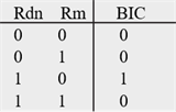
The BIC instruction performs a 32-bit bitwise AND operation on the values in Rdn and the complement of Rm and places the result into Rdn. The BIC instruction is useful for clearing bits. You specify which bits to clear in the Rm.
Rdn = Rdn & (~Rm)
Restrictions
- Rdn and Rm must be R0 to R7.
Condition Flags
The BICS instruction updates the N and Z flags according to the result, Rdn. It does not affect the C or V flags.
N: result is negative N = R31
Z:
result is zero ![]()
Examples
MOVS R7, #0x25 //mask selects bits 5,2,0
BICS R1, R7 //R1=R1&(~R7), clears bits 5,2,0
MOVS R2, #0x0F //mask selects bits 3,2,1,0
BICS R0, R0, R2 //R0=R0&(~R2), clears bits 3,2,1,0
BKPT
Breakpoint
Syntax
BKPT #imm8
Machine code
|
15-8 |
7-0 |
|
|
|
10111110 |
imm8 |
|
|
Operation
The BKPT instruction causes a breakpoint if the debugger supports the operation. Otherwise, BKPT will cause a hardfault. The imm8 value is ignored by the ARM hardware, but it can be recovered by debugger software. The constant imm8 can be any value 0 to 255.
Restrictions
- Causes a hardfault if no debugger support.
Condition Flags
The BKPT instruction does not modify any condition code flags.
Examples
BKPT #1
BKPT // same as BKPT #0
BL
Branch link (call subroutine)
Syntax
BL label // branch to subroutine at label
where label will be encoded as a PC-relative expression.
Machine code
|
31-27 |
26 |
25-16 |
15-14 |
13 |
12 |
11 |
10-0 |
|
11110 |
S |
imm10 |
1 1 |
J1 |
1 |
J2 |
imm11 |
Let I1 be NOT(J1 EOR S). Let I2 be NOT(J2 EOR S). The 32-bit target address will be
PC+Sign extend (S:I1:I2:imm10:imm11:0)
Operation
BL is the call to subroutine instruction. The address of the subroutine is specified by the label. The BL instruction also saves the return address (the address of the next instruction) in the Link Register (LR), Register R14. Bit 0 of the LR will always be 1, so the machine remains in Thumb mode. The range of the BL instruction is -16 MB to +16 MB from the current instruction.
Restrictions
- Label must be halfword-aligned
Condition Flags
This instruction does not change the flags.
Examples
BL Func //call to Func, return address in LR
//example subroutine
Func: PUSH {LR} //save LR
//body of Func subroutine
BL Help //call Help function, return address in LR
POP {PC} //return
Help:
// body of Help function
BX LR
BLX
Branch link indirect (call subroutine)
Syntax
BLX Rm4 // branch to subroutine indirect specified by Rm4
Machine code
|
15-7 |
6-3 |
2-0 |
|
|
|
010001111 |
Rm4 |
000 |
|
|
Operation
BLX is an indirect call to subroutine instruction. The address of the subroutine is specified by the register Rm4. Bit[0] of the value in Rm4 must be 1, but the address to which to branch is obtained using bits 31-1 of Rm4. The BLX instruction also saves the return address (the address of the next instruction) in the Link Register (LR), register R14. Bit 0 of the LR will always be 1, so the machine remains in Thumb mode.
Restrictions
- Rm4 should be R0 to R12.
- Unpredictable behavior occurs when Rm4 is R13 R14 or R15
Condition Flags
This instruction does not change the flags.
Examples
.align 2
FList: .long Fun0,Fun1,Fun2,Fun3 //pointers to four functions
FListaddr: .long FList
//Assume R2 contains an index I from 0 to 3
//For example, if R2 is 2, it will call Fun2
LDR R1, FListaddr //R1 points to list of functions
LSLS R3,R2,#2 //R3=4*I
ADDS R4,R1,R3 //R4=FList+4*I
LDR R0,[R4] //R0 points to subroutine to execute
MOVS R5,#1
ORRS R0,R0,R5 //set thumb bit
BLX R0 //call subroutine, return address in LR
//end of example
Fun0: //body of function 0
BX LR
Fun1: //body of function 1
BX LR
Fun2: //body of function 2
BX LR
Fun3: //body of function 3
BX LR
BX
Branch indirect
Syntax
BX Rm3 // branch indirect to location specified by Rm3
Machine code
|
15-7 |
6-3 |
2-0 |
|
|
|
010001110 |
Rm3 |
000 |
|
|
Operation
This is a branch indirect instruction, with the branch address indicated in Rm3. Bit[0] of the value in Rm3 must be 1, but the address to which to branch is obtained using bits 31-1 of Rm3. BX LR is often used as a return from subroutine. Invoking an interrupt service routine will set LR to 0xFFFFFFF9. Executing BX LR with LR equal to 0xFFFFFFF9 will cause a return from interrupt (popping 8 registers off the stack).
Restrictions
- Rm3 should be R0-R12 or R14.
- Unpredictable behavior occurs when Rm3 is R13 or R15
- Hardfault occurs if Bit[0] of Rm3 is 0.
Condition Flags
This instruction does not change the flags.
Examples
// Inputs: x in R0
// y in R1
// Outputs: z = 4*x+y in R0
Linear:
LSLS R0,#2 //R0=4*x
ADDS R0,R0,R1 //R0=4*x+y
BX LR //return from subroutine
SysTick_Handler:
// body of ISR
BX LR //return from interrupt
CMP
32-bit Compare
Syntax
CMP Rn, Rm // Rn-Rm, set flags
CMP Rn, #imm8 // Rn-imm8, set flags
Machine code
|
15-6 |
5-3 |
2-0 |
|
|
|
0100001010 |
Rm |
Rn |
|
|
|
15-11 |
10-8 |
7-0 |
|
|
|
00101 |
Rn |
imm8 |
|
|
Operation
These instructions compare the value in a register Rn with either Rm or imm8. imm8 is a constant from 0 to 255. They update the condition flags on the result, but do not write the result to a register. The CMP instruction subtracts the value of Rm or imm8 from the value in Rn. This is the same as a SUBS instruction, except that the result is discarded. This instruction can be followed by a conditional branch.
Restrictions
- Rn and Rm must be R0 to R7.
Condition Flags
Let X be the value of Rn Let M be the value of Rm or imm8 . These instructions update the N, Z, C and V flags according to the result, R=X-M.
N: result is negative N = R31
Z:
result is zero ![]()
V: signed overflow ![]()
C: unsigned overflow ![]()
Examples
CMP R2, #64
BGT gothere //branch to gothere if R2>64 (signed)
CMP R2, R3
BLO gothere //branch to gothere if R2<R3 (unsigned)
CPS
Change Processor State
Syntax
CPSIE I //Clears the Priority Mask Register (PRIMASK)
CPSIE F //Clears the Fault Mask Register (FAULTMASK)
CPSID I //Sets the Priority Mask Register (PRIMASK)
CPSID F //Sets the Fault Mask Register (FAULTMASK)
Machine code
|
15-0 |
|
|
|
1011011001100010 |
CPSIE I |
|
|
1011011001100001 |
CPSIE F |
|
|
1011011001110010 |
CPSID I |
|
|
1011011001110001 |
CPSID F |
|
Operation
CPS changes the PRIMASK and FAULTMASK special register values.
Restrictions
- None.
Condition Flags
This instruction does not change the flags.
Examples
CPSID I //Set I, disable interrupts
CPSIE I //Clear I, enable interrupts
EOR
32-bit Logical Exclusive OR
 Syntax
EORS Rdn, Rm
EORS Rdn, Rdn, Rm
Machine code
|
15-6 |
5-3 |
2-0 |
|
|
|
0100000001 |
Rm |
Rdn |
|
|
Operation
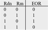
The EORS instruction performs a 32-bit bitwise exclusive or operation on the values in Rdn and Rm and places the result into Rdn. The EOR instruction is useful for toggling bits. You specify which bits to toggle in the Rm.
Rd = Rn ^ Rm
Restrictions
- Rdn and Rm must be R0 to R7.
Condition Flags
The EORS instruction updates the N and Z flags according to the result, Rdn. It does not affect the C or V flags.
N: result is negative N = R31
Z:
result is zero ![]()
Example
TogglePA2:
LDR R1, GPIOA_DOUT31_0 //R1 points to output register
LDR R2, [R1] //read all data of Port A
MOVS R3, #0x04
EORS R2, R2, R3 //R2 = R2^~0x04 (toggle bit 2)
STR R2, [R1] //update Port A
BX LR
GPIOA_DOUT31_0: .long 0x400A1280
LDR
Load 32-bit from memory into a register
Syntax
LDR Rt, [Rn] // immediate offset EA=Rn
LDR Rt, [Rn,#n5] // immediate offset EA=Rn+n5
LDR Rt, [SP,#n8] // immediate offset EA=SP+n8
LDR Rt, [Rn,Rm] // register offset EA=Rn+Rm
LDR Rt, label2 // read contents at label2, PC rel, EA=PC+relative
LDR Rt, =number // Rt=number, PC relative, EA=PC+relative
Machine code
|
15-11 |
10-6 |
5-3 |
2-0 |
|
|
01101 |
imm5 |
Rn |
Rt |
LDR Rt,[Rn,#n5] |
|
15-11 |
10-8 |
7-0 |
|
|
10011 |
Rt |
imm8 |
LDR Rt,[SP,#n8] |
|
15-9 |
8-6 |
5-3 |
2-0 |
|
|
0101100 |
Rm |
Rn |
Rt |
LDR Rt,[Rn,Rm] |
|
15-11 |
10-8 |
7-0 |
|
|
01001 |
Rt |
imm8 |
LDR Rt,label2 |
Operation
LDR instructions copy values from memory into registers. Immediate offset n5 adds the offset value (0 to 124, in multiples of 4) to the value of Rn to get the effective address. Immediate offset n8 adds the offset value (0 to 1020, in multiples of 4) to the value of SP to get the effective address. The address register Rn SP or PC is unaltered. When using PC-relative addressing, the label2 must be within 0 to +1020.
Restrictions
- Rt Rn and Rm must be R0 to R7.
- The effective address (EA) must be word aligned.
Condition Flags
These instructions do not change the flags.
Examples
.equ N,12
LDR R7, [R6] //Load 32-bit from R6 address to R7
LDR R1, [R2,#8] //Load 32-bit from (R2+8) address to R1
LDR R5, [SP,#N] //Load 32-bit from (SP+12) address to R5
LDR R0, Pi //R0=314159 (PC relative)
LDR R0, =314159 //R0=314159 (PC relative)
.align 4
Pi: .long 314159
LDRB
Load 8-bit from memory into a register
Syntax
LDRB Rt, [Rn] // immediate offset EA=Rn
LDRB Rt, [Rn,#imm5] // immediate offset EA=Rn+imm5
LDRB Rt, [Rn,Rm] // register offset EA=Rn+Rm
LDRSB Rt, [Rn,Rm] // register offset EA=Rn+Rm
Machine code
|
15-11 |
10-6 |
5-3 |
2-0 |
|
|
01111 |
imm5 |
Rn |
Rt |
LDRB Rt,[Rn,#imm5] |
|
15-9 |
8-6 |
5-3 |
2-0 |
|
|
0101100 |
Rm |
Rn |
Rt |
LDRB Rt,[Rn,Rm] |
|
0101011 |
Rm |
Rn |
Rt |
LDRSB Rt,[Rn,Rm] |
Operation
The LDRB instruction reads an 8-bit value from memory, zero-pads the 8-bit value, and puts into the 32-bit value into the target register, Rt. The LDRSB instruction will sign-extend the 8-bit values. For example, the LDRSB instruction will convert the 8-bit value 127 (0x7F) into 0x0000007F, and will convert the 8-bit value -128 (0x80) into 0xFFFFFF80. Immediate offset imm5 adds the offset value (0 to 31) to the value of Rn to get the effective address. The effective address need not be aligned.
Restrictions
- Rt Rn and Rm must be R0 to R7.
Condition Flags
These instructions do not change the flags.
Examples
LDRB R7, [R6] //Load 8-bit unsigned from R6 address to R7
LDRB R1, [R2,#5] //Load 8-bit unsigned from (R2+5) address to R1
LDRSB R0, [R1,R2] //Load 8-bit signed from (R1+R2) address to R0
LDRH
Load 16-bit from memory into a register
Syntax
LDRH Rt, [Rn] // immediate offset EA=Rn
LDRH Rt, [Rn,#h5] // immediate offset EA=Rn+h5
LDRH Rt, [Rn,Rm] // register offset EA=Rn+Rm
LDRSH Rt, [Rn,Rm] // register offset EA=Rn+Rm
Machine code
|
15-11 |
10-6 |
5-3 |
2-0 |
|
|
10001 |
imm5 |
Rn |
Rt |
LDRH Rt,[Rn,#h5] |
|
15-9 |
8-6 |
5-3 |
2-0 |
|
|
0101101 |
Rm |
Rn |
Rt |
LDRH Rt,[Rn,Rm] |
|
0101111 |
Rm |
Rn |
Rt |
LDRSH Rt,[Rn,Rm] |
Operation
The LDRH instruction reads a 16-bit unsigned value from memory, zero-pads the 16-bit value, and puts into the 32-bit value into the target register, Rt. The LDRSH instruction will sign-extend the 16-bit values. For example, the LDRSH instruction will convert the 16-bit value 32767 (0x7FFF) into 0x00007FFF, and will convert the 16-bit value -32768 (0x8000) into 0xFFFF8000. Immediate offset h5 adds the offset value (0 to 62, in multiples of 2) to the value of Rn to get the effective address.
Restrictions
- Rt Rn and Rm must be R0 to R7.
- The effective address (EA) must be halfword aligned.
Condition Flags
These instructions do not change the flags.
Examples
LDRH R7, [R6] //Load 16-bit unsigned from R6 address to R7
LDRH R1, [R2,#6] //Load 16-bit unsigned from (R2+6) address to R1
LDRSH R0, [R1,R2] //Load 16-bit signed from (R1+R2) address to R0
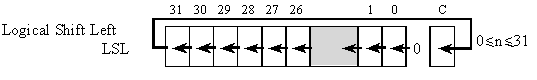
LSL
32-bit Logical Shift Left
Syntax
LSLS Rdn, Rs
LSLS Rdn, Rdn, Rs
LSLS Rd, Rm, #n
where n is the shift length (0 to 31).
Machine code
|
15-11 |
10-6 |
5-3 |
2-0 |
|
|
00000 |
imm5 |
Rm |
Rd |
LSLS Rd,Rm,#n |
|
15-6 |
5-3 |
2-0 |
|
|
|
0100000010 |
Rm |
Rdn |
LSLS Rdn,Rm |
|
Operation
LSL moves the bits in the register Rm to the left by the number of places specified by constant n or register Rs. This instruction can be used for signed and unsigned integers. Zeros are shifted into the right side. Shift left is similar to multiplication by a power of 2. The result is written to Rd, and the value in register Rm remains unchanged.
Rdn = Rdn << Rm (signed or unsigned)
Rd = Rm << n (signed or unsigned)
Restrictions
- Rd Rdn and Rm must be R0 to R7.
Condition Flags
The LSLS instruction updates the N and Z flags according to the result. The C flag is updated to the last bit shifted out, except when the shift length is 0.
N: result is negative N = R31
Z:
result is zero ![]()
Examples
LSLS R7, R6, #9 //R7 = R6<<9 (similar to R7=R6*512)
LSLS R5, R6 //R5 = R5<<R6 (similar to R5=R5*2R6)
LSLS R5, R5, R6 //R5 = R5<<R6 (similar to R5=R5*2R6)
LSLS R0, R1, #0 //will assemble as MOVS R0,R1
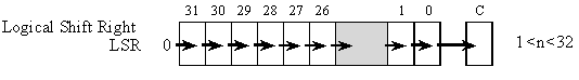
LSR
32-bit Logical Shift Right
Syntax
LSRS Rdn, Rs
LSRS Rdn, Rdn, Rs
LSRS Rd, Rm, #n
where n is the shift length (1 to 32).
Machine code
|
15-11 |
10-6 |
5-3 |
2-0 |
|
|
00001 |
imm5 |
Rm |
Rd |
LSRS Rd,Rm,#n |
|
15-6 |
5-3 |
2-0 |
|
|
|
0100000011 |
Rm |
Rdn |
LSRS Rdn,Rm |
|
Operation
LSR moves the bits in the register Rm to the right by the number of places specified by constant n or register Rs. Values are unsigned integers, so zeros are shifted into bit 31. Shift right is similar to unsigned division by a power of 2. The result is written to Rd, and the value in register Rm remains unchanged.
Rdn = Rdn >> Rm (unsigned)
Rd = Rm >> n (unsigned)
Restrictions
- Rd Rdn and Rm must be R0 to R7.
Condition Flags
The LSRS instruction updates the N and Z flags according to the result. The C flag is updated to the last bit shifted out, except when the shift length is 0.
N: result is negative N = R31
Z:
result is zero ![]()
Examples
LSRS R7, R5, #9 //R7 = R5>>9 (similar to R7=R5/512)
LSRS R4, R4, R6 //R4 = R4>>R6 (similar to R4=R4/2R6)
MOV
32-bit Move
Syntax
MOV Rd2, Rm2 // move contents of Rm2 into Rd2
MOVS Rd, Rm // move contents of Rm into Rd, set flags
MOVS Rd, #imm8 // move contents of imm8 into Rd, set flags
Machine code
|
15-8 |
7 |
6-3 |
2-0 |
|
|
|
01000110 |
D |
Rm2 |
Rd1 |
MOV Rd2,Rm2 |
|
|
15-6 |
5-3 |
2-0 |
|
|
|
0000000000 |
Rm |
Rd |
MOVS Rd,Rm |
|
|
15-11 |
10-8 |
7 -0 |
|
|
|
00100 |
Rd |
imm8 |
MOVS Rd,#imm8 |
|
where Rd2 is formed by combining D:Rd1
Operation
The MOV instruction copies the value from Rm2 into Rd2, without setting flags. The registers Rm2 and Rd2 can be any of the 16 registers. MOVS copies the value from Rm/imm8 into Rd, and does set flags. The constant imm8 can be any value from 0 to 255.
Restrictions
- Rd and Rm must be R0 to R7.
Condition Flags
The MOVS instruction will update the N and Z flags according to the value. It does not affect the V or C flags.
N: result is negative N = R31
Z:
result is zero ![]()
Examples
MOVS R1, #10 // R11=10, N and Z flags get updated
MOVS R0, R5 // R0=R5, N and Z flags get updated
MOV R7, SP // R7=SP
MUL
32-bit Multiplication
Syntax
MULS Rdn, Rm // Multiply Rdn = Rdn*Rm
MULS Rdn, Rdn, Rm // Multiply Rdn = Rdn*Rm
Machine code
|
15-6 |
5-3 |
2-0 |
|
|
|
0100001101 |
Rm |
Rdm |
MULS Rdn,Rdn,Rm |
|
Operation
The MULS instruction multiplies the values from Rdn and Rm, and places the least-significant 32 bits of the result in Rdn. The result does not depend on whether the operands are signed or unsigned. This instruction is useful for implementing digital filters and other digital signal processing.
Rdn = Rdn * Rm
Restrictions
- Rdn and Rm must be in the range R0 to R7.
Condition Flags
The MULS instruction will update the N and Z flags according to the result, Rdn. It does not affect the C and V flags.
N: result is negative N = R31
Z:
result is zero ![]()
Examples
MULS R1, R1, R5 //R1 = R1 * R5, sets N and Z flags
MULS R0, R1 //R0 = R0 * R1, sets N and Z flags
NOP
No operation
Syntax
NOP
Machine code
|
15-0 |
|
|
|
1011 1111 0000 0000 |
|
|
Operation
The NOP instruction performs no operation. The timing effects of the NOP instruction are not guaranteed. It can increase execution time, leave it unchanged, or even reduce it. The proper way to implement time delays is to use one of the hardware timers.
Restrictions
- None
Condition Flags
The NOP instruction does not modify any condition code flags.
Examples
NOP
ORR
32-bit Logical OR
Syntax
ORRS Rdn, Rm //Rdn = Rdn | Rm
ORRS Rdn, Rdn, Rm //Rdn = Rdn | Rm
Machine code
|
15-6 |
5-3 |
2-0 |
|
|
|
0100001100 |
Rm |
Rdn |
|
|
Operation
The ORR instruction performs a 32-bit bitwise OR operation on the values in Rdn and Rm and places the results into Rdn. The ORR instruction is useful for setting bits. You specify which bits to set in the Rm.
Restrictions
- Rdn and Rm must be in the range R0 to R7.
Condition Flags
The ORRS instruction will update the N and Z flags according to the result, Rdn. It does not affect the C and V flags.
N: result is negative N = R31
Z:
result is zero ![]()
Examples
MOVS R2,#0x05
ORRS R7, R2 //R7 = R7 | R2, sets bits 2,0, sets N, Z
MOVS R3,#0x10
ORRS R5, R5, R3 //R5 = R5 | R3, sets bit 4, sets N, Z
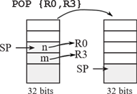
POP
Pop registers off a LIFO stack
 |
Syntax
POP {reglist}
reglist is a non-empty list of registers, enclosed in braces.
It can contain register ranges. It must be comma separated
if it contains more than one register or register range.
Machine code
|
15-9 |
8 |
7-0 |
|
|
|
1011110 |
P |
register list |
|
|
where P means POP PC, and the register list specifies R0 to R7. For example POP {R0,R3} is 0xBC09, where bit 0 in the machine code specifies R0, and bit 3 specifies R3.
Operation
The SP points to the top of the stack, containing the data value to be popped next. POP loads registers from the stack in order of increasing register numbers, with the lowest numbered register using the lowest memory address and the highest numbered register using the highest memory address. POP reads data from the memory based on SP, and increments the SP by 4 times the number of values popped. Incrementing the SP has the effect of removing the data from the stack.
Restrictions
- reglist is restricted to R0-R7 and PC.
- When PC is in reglist in a POP instruction:
- Bit[0] of the value loaded to the PC must be 1 for correct execution,
- A branch occurs to this halfword-aligned address.
Condition Flags
This instruction does not change the flags.
Examples
POP {R5} //pop 32 bits from stack and place it in R5
POP {R0,R4-R7} //pop 5 words from stack and place into R0,R4,R5,R6,R7
POP {R2,PC} //pop 2 words from stack and place into R2, PC
POP {R0-R2,PC} //pop 4 words from stack and place into R0,R1,R2,PC
//example subroutine
Func: PUSH {R4-R7,LR} //save registers
//body of subroutine
POP {R4-R7,PC} //restore registers and return
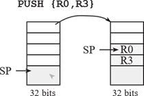
PUSH
Push registers onto a LIFO stack
 |
Syntax
PUSH {reglist}
where reglist is a non-empty list of registers, enclosed
in braces. It can contain register ranges. It must be comma
separated if it contains more than one register or register range.
Machine code
|
15-9 |
8 |
7-0 |
|
|
|
1011010 |
M |
register list |
|
|
where M means PUSH LR, and the register list specifies R0 to R7. For example PUSH {R0,LR} is 0xB501, where bit 0 in the machine code specifies R0, and bit 8 specifies LR.
Operation
The SP points to the top of the stack, containing the data value to be popped next. PUSH stores registers on the stack in order of decreasing register numbers, with the highest numbered register using the highest memory address and the lowest numbered register using the lowest memory address. PUSH first decrements the SP by 4 times the number values to be pushed and then writes data to the memory based on SP. Decrementing the SP has the effect of placing new the data onto the stack.
Restrictions
- reglist is restricted to R0-R7 and LR.
- When LR is in reglist in a PUSH instruction:
- Bit[0] will always be 1,
- Bits[31-1] are the halfword-aligned return address.
Condition Flags
This instruction does not change the flags.
Examples
//example subroutine, with local variable
Func: PUSH {R4-R7,LR} //save registers
.equ sum,0 //32-bit local variable, stored on the stack
MOVS R0,#0
PUSH {R0} //allocate and initialize a local variable
//body of subroutine
LDR R1,[SP,#sum] //R1=sum
ADD R1,R0 //R1=R0+sum
STR R1,[SP,#sum] //sum=R0+sum
//end of subroutine
ADD SP,#4 //deallocate sum
POP {R4-R7,PC} //restore registers and return
RSB
32-bit Reverse Subtraction
Syntax
RSBS Rd, Rn, #0 // Rd = 0-Rn
Machine code
|
15-6 |
5-3 |
2-0 |
|
|
|
0100001001 |
Rn |
Rd |
RSBS Rd,Rn,#0 |
|
Operation
The RSB instruction subtracts the value in Rn from 0 and stores the sum in Rd.
Rd = 0 - Rn
This is useful to implement a 2’s complement negate.
Restrictions
- Rd and Rn must be R0 to R7.
Condition Flags
The RSBS instruction updates the N, Z, C and V flags according to the result. R=M-X, where X is initial register value, M is 0, and R is the final register value.
N: result is negative N = R31
Z:
result is zero ![]()
V: signed overflow V = M31& (~X31)& (~R31) | (~M31)&X31& R31
C: unsigned overflow C = ~( (~M31& X31 ) | X31& R31 | R31&(~M31) )
Examples
.macro Neg,reg
RSBS \reg,\reg,#0
.endm
RSBS R7, R6, #0 //R7 = -R6, negate, sets the flags
Neg R3 //same as RSBS R3,R3,#0
STR
Store 32-bit value from register into memory
Syntax
STR Rt, [Rn] // immediate offset EA=Rn+offset
STR Rt, [Rn,#n5] // immediate offset EA=Rn+offset+n5
STR Rt, [SP,#n8] // immediate offset EA=SP+n8
STR Rt, [Rn,Rm] // register offset EA=Rn+Rm
Machine code
|
15-11 |
10-6 |
5-3 |
2-0 |
|
|
01100 |
imm5 |
Rn |
Rt |
STR Rt,[Rn,#n5] |
|
15-11 |
10-8 |
7-0 |
|
|
10010 |
Rt |
imm8 |
STR Rt,[SP,#n8] |
|
15-9 |
8-6 |
5-3 |
2-0 |
|
|
0101000 |
Rm |
Rn |
Rt |
STR Rt,[Rn,Rm] |
Operation
STR instructions copy 8-bit 16-bit or 32-bit values from registers to memory. Immediate offset n5 adds the offset value (0 to 124, in multiples of 4) to the value of Rn to get the effective address. Immediate offset n8 adds the offset value (0 to 1020, in multiples of 4) to the value of SP to get the effective address. The address register Rn or SP is unaltered.
Restrictions
- Rt Rn and Rm must be R0 to R7.
- The effective address (EA) must be word aligned.
Condition Flags
These instructions do not change the flags.
Examples
STR R2, [R7,#4] //32-bit store value of R2 into address R7+4
STR R3, [SP,#8] //32-bit store value of R3 into address SP+8
STR R0, [R1,R2] //32-bit store value of R0 into address R1+R2
STRB
Store 8-bit from register into memory
Syntax
STRB Rt, [Rn] // immediate offset EA=Rn
STRB Rt, [Rn,#imm5] // immediate offset EA=Rn+imm5
STRB Rt, [Rn,Rm] // register offset EA=Rn+Rm
Machine code
|
15-11 |
10-6 |
5-3 |
2-0 |
|
|
01110 |
imm5 |
Rn |
Rt |
STRB Rt,[Rn,#imm5] |
|
15-9 |
8-6 |
5-3 |
2-0 |
|
|
0101010 |
Rm |
Rn |
Rt |
STRB Rt,[Rn,Rm] |
Operation
The STRB instruction stores an 8-bit value from register, discarding bits 31-8, and puts into the 8-bit value into memory. Immediate offset imm5 adds the offset value (0 to 31) to the value of Rn to get the effective address. The effective address need not be aligned.
Restrictions
- Rt Rn and Rm must be R0 to R7.
Condition Flags
These instructions do not change the flags.
Examples
STRB R7, [R6] //store low 8 bits of R7 to address specified by R6
STRB R1, [R2,#5] //store low 8 bits of R1 to address specified by R2+5
STRB R0, [R3,R4] //store low 8 bits of R0 to address specified by R3+R4
STRH
Store 16-bit from register into memory
Syntax
STRH Rt, [Rn] // immediate offset EA=Rn
STRH Rt, [Rn,#n5] // immediate offset EA=Rn+n5
STRH Rt, [Rn,Rm] // register offset EA=Rn+Rm
Machine code
|
15-11 |
10-6 |
5-3 |
2-0 |
|
|
10000 |
imm5 |
Rn |
Rt |
STRH Rt,[Rn,#n5] |
|
15-9 |
8-6 |
5-3 |
2-0 |
|
|
0101001 |
Rm |
Rn |
Rt |
STRH Rt,[Rn,Rm] |
Operation
The STRH instruction stores a 16-bit value from a register, discarding bits 31-16, and stores into the 16-bit value into memory. Immediate offset imm5 adds the offset value (0 to 62, in multiples of 2) to the value of Rn to get the effective address.
Restrictions
- Rt Rn and Rm must be R0 to R7.
- The effective address (EA) must be halfword aligned.
Condition Flags
These instructions do not change the flags.
Examples
STRH R7,[R6] //store low 16 bits of R7 to address specified by R6
STRH R1,[R2,#6] //store low 16 bits of R1 to address specified by R2+6
STRH R0,[R3,R4] //store low 16 bits of R0 to address specified by R3+R4
SUB
32-bit Subtraction
Syntax
SUBS Rd, Rn, #imm3 // Rd = Rn-imm3
SUBS Rdn, #imm8 // Rdn = Rdn-imm8
SUBS Rd, Rn, Rm // Rd = Rm-Rn
SUB SP, SP, #imm7w // SP = SP-imm7w
Machine code
|
15-9 |
8-6 |
5-3 |
2-0 |
|
|
0001111 |
imm3 |
Rn |
Rd |
SUBS Rd,Rn,#imm3 |
|
15-11 |
10-8 |
7-0 |
|
|
|
00111 |
Rdn |
imm8 |
SUBS Rdn,#imm8 |
|
|
15-9 |
8-6 |
5-3 |
2-0 |
|
|
0001101 |
Rm |
Rn |
Rd |
SUBS Rd,Rn,Rm |
|
15-7 |
6-0 |
|
|
|
101100001 |
imm7 |
SUB SP,#imm7w |
|
Operation
The SUB instruction adds subtracts 32-bit values and stores the difference into the register closest to the op code. imm3 is a constant from 0 to 7. imm8 is a constant from 0 to 255. Values added to the SP must be powers of 4 (SP must be word aligned). So, imm7w is a constant from 0 to 508.
Restrictions
- Rd, Rm, and Rn must be R0 to R7.
Condition Flags
The SUBS instruction updates the N, Z, C and V flags according to the result. R=X-M, where X is initial register value, M is the second operand, and R is the final register value.
N: result is negative N = R31
Z:
result is zero ![]()
V: signed overflow ![]()
C:
unsigned overflow ![]()
Examples
SUBS R7, R5, #2 //R7=R1-2, sets the flags on the result
SUBS R2, R1, R3 //R2=R1-R3, sets the flags on the result
SUBS R6, #240 //R6=R6-240, sets the flags on the result
SUB SP, #8 // allocate two local variables (SP=SP-8)
SVC
Supervisor call
Syntax
SVC #imm8 // software interrupt
Machine code
|
15-8 |
7-0 |
|
|
|
11011111 |
imm8 |
|
|
Operation
The SVC instruction invokes a software interrupt, which will be handled by the SVC_Handler interrupt service routine. This instruction pushes the same 8 registers on the stack as a hardware interrupt, and sets the LR to 0xFFFFFFF9. The imm8 value is ignored by the ARM hardware, but it can be recovered by software. The constant imm8 can be any value 0 to 255. SVC is used to call operating system functions.
Restrictions
- Causes a hardfault if SVC_Handler is not defined.
Condition Flags
The SVC instruction does not modify any condition code flags.
Examples
SVC #1
WFI
Wait for interrupt
Syntax
WFI // sleep and wait for interrupt
Machine code
|
15-0 |
|
|
|
1011 1111 0011 0000 |
|
|
Operation
The WFI instruction halts execution, enters a low power state, and waits for an interrupt. Execution resumes after the next interrupt service routine completes. WFI is used to save power.
Restrictions
- None.
Condition Flags
The WFI instruction does not modify any condition code flags.
Examples
WFI